
The system consists of a hydraulic governor unit and 4 wheel sensors.
The regulator block contains an electronic control device (ECU), 8 hydraulic solenoid valves (2 for each brake) and an electrically driven pump.
The solenoid valves are controlled by the ECU, which receives signals from four sensors located on each wheel of the vehicle (the front sensors are mounted on the hubs and the rear ones are attached to the caliper mounting suspension), which control the rotation speed of each wheel. By comparing these signals, the ECU can determine the vehicle's speed. By comparing the speed of a single wheel with the average speed of the vehicle, the control unit determines the state of wheel lock. When the wheel approaches blocking, the brake fluid pressure is too high, so the pressure in the caliper is reduced by a signal from the control unit. This happens until the wheel starts to accelerate again. Then the valves close again and the pressure created by the brake pedal begins to act again. However, the pressure value in the brake circuit of this wheel is not higher than the total pressure in the system. ABS operation during hard braking is repeated on each wheel until force is applied to the pedal or the vehicle stops.
In the event of any malfunction in the ABS system, it is disabled. In this case, the ABS warning lamp on the instrument panel comes on and the braking system operates normally.
Regulator block
Removing
1. Remove the negative terminal from the battery.
2. Release the bracket and disconnect the main electrical connector from the regulator block. Unscrew the nut and disconnect the ground bar from the unit.
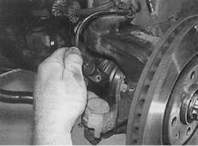
3. Mark the brake pipes, unscrew the connecting nuts and disconnect the pipes from the regulator block.
4. Unscrew nuts of fastening of a regulator and take it from a motor compartment.
Installation
1. Reinstall the regulator and secure with nuts.
2. Connect the brake pipes and tighten the fastening nuts to the required torque.
3. Connect the electrical connector and ground bar to the regulator block.
4. Remove air from the brake system.
Electronic control device (ecu)
Removing
1. The ECU can be removed from the controller while the controller remains on the vehicle. Remove the battery and its stand.
2. Release the bracket and disconnect the electrical connector from the ECU.
3. Unscrew the mounting bolts and remove the ECU from the engine compartment.
Installation
1. Install the ECU to the regulator and secure with bolts.
2. Connect the electrical connector to the unit and install the battery.
Front wheel sensor (wheel rotation sensor)
Removing
1. Remove the negative terminal from the battery.
2. Raise the front of the car and secure it on stands. Remove the wheel.
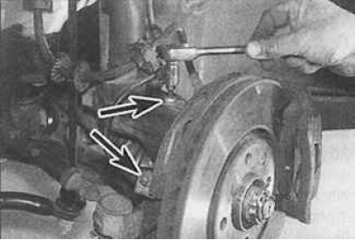
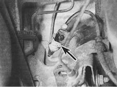
3. Loosen the nut and bolt (indicated by arrows).
4. Remove the protective shield from the sensor.
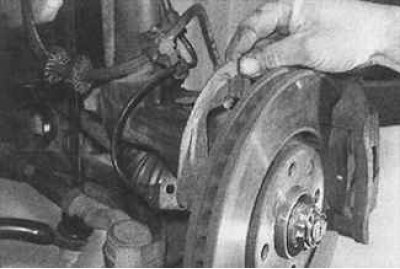
5. Disconnect the electrical connector located on the wheel speed sensor wire.
6. Remove the wheel speed sensor mounting bolt.
7. Remove the sensor from the steering knuckle.
Installation
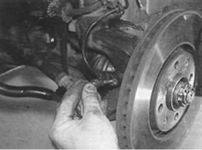
1. Make sure that the mating surfaces of the sensor and steering knuckle are clean, and grease the hole for installing the sensor in the steering knuckle with a small layer of grease.
2. Check that the tip of the sensor is clean and fits freely into the steering knuckle.
3. Lubricate the threads of the sensor mounting bolt with an anti-tightening agent (Loctite Frenetanch). Install the sensor in the steering knuckle and secure with a bolt.
4. Connect the electrical connector to the sensor.
5. Install the protective shield to the sensor and secure with a nut and bolt.
Rear wheel sensor (wheel rotation sensor)
Removing
1. Raise the rear of the car and secure it on stands. Remove the corresponding rear wheel.
2. Disconnect the electrical connector (indicated by an arrow) from the sensor.
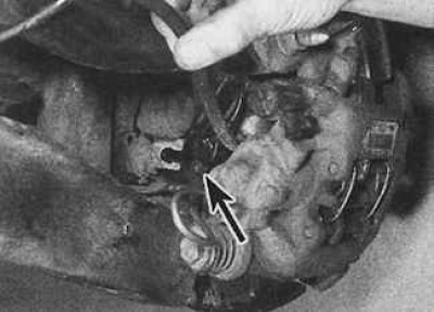
3. Unscrew the bolt and remove the sensor (indicated by an arrow) from the nest.
Installation
1. Make sure the mating surfaces of the sensor and hub are clean. Apply a thin film of lubricant to the sensor mounting hole.
2. Make sure the sensor tip is clean and fits easily into the hub.
3. Lubricate the threads of the sensor mounting bolt with an anti-tightening agent (Loctite Frenetanch). Install the sensor in the socket and secure with a bolt.
4. Connect the sensor electrical connector.