



Table of contents: Magnetti Marelli 8P15 fuel injection…🠇 Magnetti Marelli 8P22 fuel injection…🠇 Bosch MP 5.1 Motronic fuel injection…🠇 Bosch MP 3.2 fuel injection system 🠇 Bosch MP 7.3 fuel injection system 🠇 Idling speed and CO content 🠇
Magnetti Marelli 8P15 fuel injection system. 1.8-liter engine
This multi-point fuel injection system has a static ignition system and is equipped with knock sensors. The ignition timing, as well as the mixture composition, is regulated by an electronic control unit. The amount of fuel injected depends on the duration of opening of the fuel injector. The duration of opening of the fuel injector, in turn, depends on the engine load, which is recorded by the pressure sensor in the intake manifold and the crankshaft speed sensor mounted on the flywheel.
All four injectors open simultaneously at every engine revolution and inject fuel into the intake manifold. While driving, the injection system control unit makes appropriate adjustments to ensure that the system's operation corresponds to the operating load on the engine and the road conditions. The operation of the injection system depends on information received from various system components. The operation of the fuel injection system is determined by:
- information about the coolant temperature coming from the corresponding sensor;
- information on engine operating loads (idle, full load, transition from one mode to another, forced idle), which comes from the TDC and crankshaft speed sensor located on the flywheel;
- atmospheric pressure;
- battery voltage;
- the density of the incoming air, recorded by the intake air temperature sensor;
- information from the lambda probe;
The electronic control unit also regulates the following functions:
- changes the ignition timing and the composition of the air-fuel mixture based on the data received from the knock sensor;
- opens the valve to supply fuel vapor from the adsorber to the intake manifold;
- changes the ignition timing and the supply of additional air when the air conditioner is turned on;
- informs the driver using a warning light about the occurrence of malfunctions and failures in operation recorded by the self-diagnostic system;
- protects the engine from running at excessive speeds by disabling the ignition;
- informs the driver of the engine speed by monitoring signals on the tachometer;
- disables fuel injection (with subsequent inclusion), if the engine speed drops to 1400 rpm;
- adjusts the operation of the idle speed control drive during the engine start and idle phases.
Information about the pressure in the intake manifold is provided by a sensor located there. At the moment the ignition and starter are turned on, this sensor remembers the atmospheric pressure. This means that when the engine is running, the sensor will inform the electronic unit about changes in pressure in the intake manifold relative to the atmospheric pressure it has recorded. This sensor is supplied with 5 V power and sends an electrical signal to the control unit, the power of which depends on the pressure in the intake manifold.
The throttle position potentiometer informs the control unit of the throttle valve opening angle. This information is needed by the unit to determine the engine load. If the accelerator pedal is released, the engine is in idle mode, and a fully depressed accelerator pedal means full engine load mode. In accordance with the movement of the accelerator pedal, the processes of acceleration and acceleration, braking and the inclusion of forced idle speed are controlled.
Idle speed is adjusted by the idle speed control actuator (drive). The regulator is located in the throttle body and controls the air supply bypassing the throttle valve. This ensures the supply of additional air when the engine is cold, and the idle speed is set depending on the engine load and the coolant temperature (see illustration 2.0).
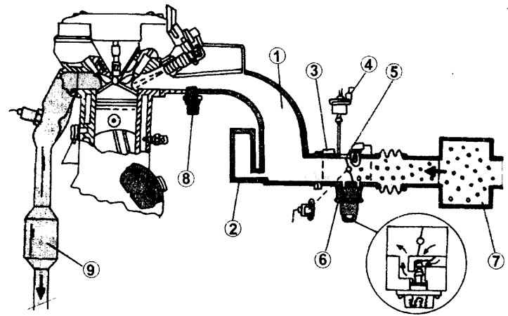
2.0 Air intake components of Magnetti Marelli and Bosch MP 5.1 fuel injection systems
1 - intake manifold
2 - resonator box
3 - idle air heater
4 - electromagnetic valve of the adsorber
5 - throttle body
6 - idle speed control actuator motor
7 - air filter
8 - intake manifold air pressure sensor
9 - catalyst
The coolant temperature sensor is located in the outlet pipe, and the intake air temperature sensor is in the air intake.
The following components are installed on the throttle body: accelerator cable, fuel pressure regulator, adsorber valve, additional air valve, brake booster, throttle position potentiometer, idle air heater, inlet air temperature sensor and idle speed control actuator motor.
As for fuel supply, the following are the main parts to be mentioned:
- fuel pump. It is installed horizontally in the fuel tank. The pump delivers fuel to the fuel filter.
- fuel filter. It is attached to the fuel tank and should be replaced after the vehicle has driven approximately 80,000 km. There is an arrow on the filter housing that should point toward the front of the engine after installation.
- adsorber. Fuel vapors generated in the fuel tank are captured by the activated charcoal of the adsorber. The valve that connects the adsorber to the fuel tank is constantly open when the engine is not running. When the ignition is turned on, the valve closes. When the engine is running, the valve opens in accordance with the "requirements" of the electronic control unit, i.e. when the conditions set in the control unit's operating program occur. When the valve opens, fuel vapors held in the adsorber are supplied to the intake manifold.
- fuel pressure reducing valve. The valve is installed on the fuel distribution line. Fuel enters the line from the fuel pump, and the pressure reducing valve maintains a constant pressure in the fuel line of 2.5 bar at idle speed and 3.0 bar at full engine load. Unused fuel is fed back to the fuel tank.
- valve injectors. Valve injectors inject fuel and simultaneously spray it directly into the intake manifold. All four injectors are activated at every engine revolution (see illustration 2.0a).
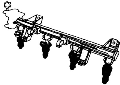
2.0a Fuel distribution line of the Magnetti Marelli and Bosch MP 5.1 fuel injection system with injectors. On the left side of the fuel line there is a fuel pressure reducing valve
Magnetti Marelli 8P22 fuel injection system
This multi-point fuel injection system has a static ignition system and is equipped with knock sensors. The ignition timing, as well as the mixture composition, is regulated by an electronic control unit. The amount of fuel injected depends on the duration of opening of the fuel injector. The duration of opening of the fuel injector, in turn, depends on the engine load, which is recorded by the pressure sensor in the intake manifold and the crankshaft speed sensor mounted on the flywheel.
All four injectors open simultaneously at every engine revolution and inject fuel into the intake manifold. While driving, the injection system control unit makes appropriate adjustments so that the system's operation corresponds to the operating loads on the engine and the road conditions. The operation of the injection system depends on information received from various system components. The operation of the fuel injection system is determined by:
- information about the coolant temperature coming from the corresponding sensor;
- information on engine operating loads (idle, full load, transition from one mode to another, forced idle), which comes from the TDC and crankshaft speed sensor located on the flywheel;
- atmospheric pressure;
- battery voltage;- the density of the incoming air, recorded by the intake air temperature sensor;
- information from the lambda probe;
- The electronic control unit also regulates the following functions: - changes the ignition timing and the composition of the air-fuel mixture based on the data received from the knock sensor;
- opens the valve to supply fuel vapor from the adsorber to the intake manifold;
- changes the ignition timing and the supply of additional air when the air conditioner is turned on;
- informs the driver using a warning light about the occurrence of malfunctions and failures in operation recorded by the self-diagnostic system;
- protects the engine from running at excessive speeds by turning off the ignition at engine speeds of 6500 rpm;
- informs the driver of the engine speed by monitoring signals on the tachometer;
- disables fuel injection (with subsequent inclusion), if the engine speed drops to 1400 rpm;
- adjusts the operation of the idle speed control drive during the engine start and idle phases.
Information about the pressure in the intake manifold is provided by a sensor located there. At the moment the ignition and starter are turned on, this sensor remembers the atmospheric pressure. This means that when the engine is running, the sensor will inform the electronic unit about changes in pressure in the intake manifold relative to the atmospheric pressure it has recorded. This sensor is supplied with 5 V power and sends an electrical signal to the control unit, the power of which depends on the pressure in the intake manifold.
The following components are installed on the throttle body: accelerator cable, fuel pressure regulator, adsorber valve, additional air valve, brake booster, throttle position potentiometer, idle air heater, inlet air temperature sensor and idle speed control actuator motor.
The throttle position potentiometer informs the control unit of the throttle valve opening angle. This information is needed by the unit to determine the engine load. If the accelerator pedal is released. then the engine is running in idle mode, and a fully depressed accelerator pedal means full engine load mode. In accordance with the movement of the accelerator pedal, the processes of acceleration and acceleration, braking and the inclusion of forced idle speed are controlled. Idle speed is adjusted by the idle speed control actuator (drive). The regulator is located in the throttle body and controls the air supply bypassing the throttle valve. This ensures the supply of additional air when the engine is cold, and the idle speed is set depending on the engine load and the coolant temperature.
The coolant temperature sensor is located in the outlet pipe, and the intake air temperature sensor is in the air intake.
The air supply to the cylinders is regulated by the throttle valve (see illustration 2.0).
As for fuel supply, the following are the main parts to be mentioned:
- fuel pump. It is installed horizontally in the fuel tank. The pump delivers fuel to the fuel filter.
- fuel filter. It is attached to the fuel tank and should be replaced after the vehicle has driven approximately 80,000 km. There is an arrow on the filter housing that should point toward the front of the engine after installation.
- adsorber. Fuel vapors generated in the fuel tank are captured by the activated charcoal of the adsorber. The valve that connects the adsorber to the fuel tank is constantly open when the engine is not running. When the ignition is turned on, the valve closes. When the engine is running, the valve opens in accordance with the "requirements" of the electronic control unit, i.e. when the conditions set in the control unit's operating program occur. When the valve opens, fuel vapors held in the adsorber are supplied to the intake manifold.
- fuel pressure reducing valve. The valve is installed on the fuel distribution line. Fuel enters the line from the fuel pump, and the pressure reducing valve maintains a constant pressure of 2.5 bar in the fuel line when the engine is idling and 3.0 bar at full engine load. Unused fuel is fed back to the fuel tank.
- valve injectors. Valve injectors inject fuel and simultaneously spray it directly into the intake manifold. All four injectors are activated at every engine revolution (see illustration 2.0b).
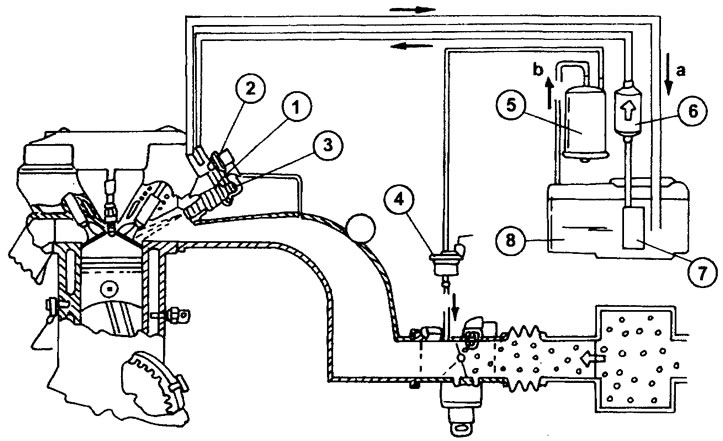
2.0b Fuel delivery components of the Magnetti Marelli fuel injection system. The letter "a" indicates the direction of fuel flow from the tank, and the letter "b" indicates the fuel return to the tank.
1 - fuel distribution line
2 - fuel pressure reducing valve
3-valve injector
4 - electromagnetic valve of the adsorber
5 - container with activated carbon
6 - fuel filter
7 - fuel pump in the tank
8 - fuel tank
Bosch MP 5.1 Motronic fuel injection system
This system is installed on 1.8-liter engines. Like the already mentioned Magnetti Marelli injection system, the Motronic system also relies on engine load information, which is recorded by the intake manifold pressure sensor, and information from the crankshaft speed sensor mounted on the flywheel (see also illustration 1.0a). The main components of Motronic are identical to the Magnetti Marelli injection system.
Bosch MP 3.2 fuel injection system
This system is equipped with a 2.0-liter engine with 8 valves and a gas turbine supercharger. In general, the system is identical to Magnetti Marelli, but has some differences (see illustration 2.0b).
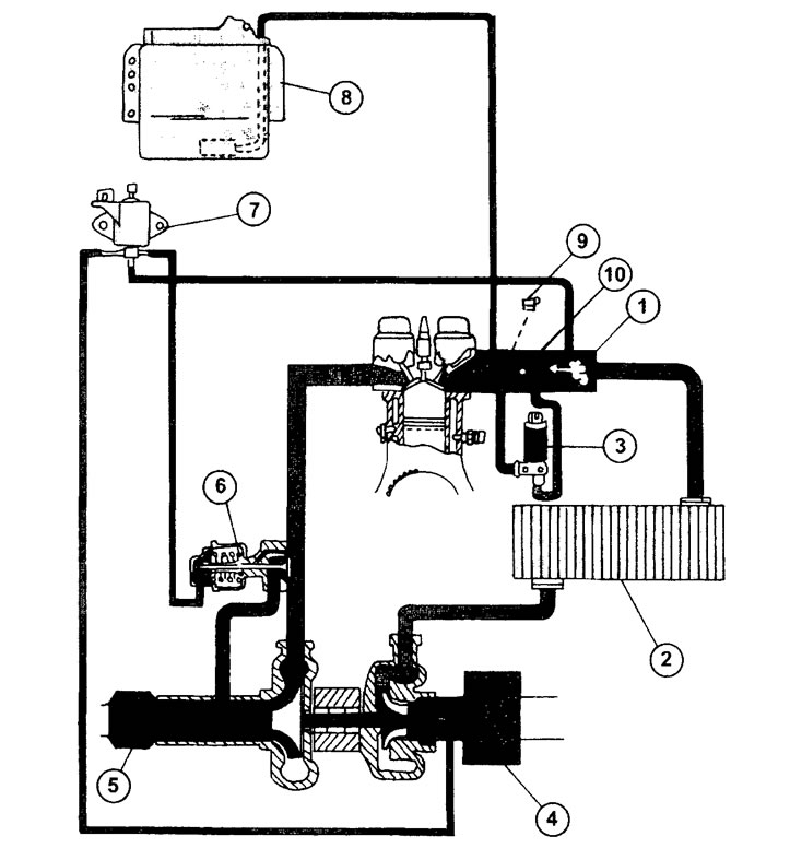
2.0v Turbocharged Engine Air Intake Components
1 - intake manifold
2 - supercharger air radiator (intercooler)
3 - idle speed control valve
4 - air filter
5 - catalyst
6 - control valve
7 - gas turbine supercharger control valve
8 - electronic control unit with intake manifold pressure sensor
9 - air heater on the throttle body
10 - throttle body
The valve injectors are installed on the fuel distribution line. They are controlled by an electronic control unit and each injects fuel individually through the valve of its cylinder at each engine revolution.
The fuel pressure regulator is located on the fuel distribution line and maintains a constant fuel pressure of 3.0 bar under any engine load.
The intake manifold has air intake channels with variable length and internal diameter, which allows for increased torque at low engine speeds.
The electronic control unit interrupts the fuel supply during forced idle with engine speed below 1280 rpm and turns it on after the engine speed increases.
To protect the engine from overspeeding, the electronic control unit disables fuel injection at 6840 rpm. The TDC sensor is mounted on the cylinder head.
Bosch MP 7.3 fuel injection system
This fuel injection system is equipped with 2.0-liter engines with 16 valves. Overall, its components are identical to the Bosch MP 3.2 system. The system itself is a sequential fuel injection system.
Idling speed and CO content
As already mentioned, the idle speed of engines with these fuel injection systems cannot be adjusted. The constant idling speed is provided by an electronic control unit, which, using the idling regulator drive, maintains the idling speed at the nominal level. The permissible deviation can be ±50 rpm, which does not affect the operation of the engine.
The CO content in the exhaust gases is automatically maintained at a set level of approximately 0.5% using a lambda probe.