



Table of contents: 5.3.1 Magnetti Marelli 8P system 🠇 5.3.2 Fuel injection system Motronic…🠇 5.3.3 Bosch MP 3.2 fuel injection…🠇
Although, as already mentioned, no independent work is carried out on the system, a brief description of individual systems is provided.
5.3.1 Magnetti Marelli 8P system
The functional diagram of this system is shown in Figure 170. The distributed injection system works with a static ignition system and a knock sensor. The electronic control unit regulates the mixture composition and ignition timing.
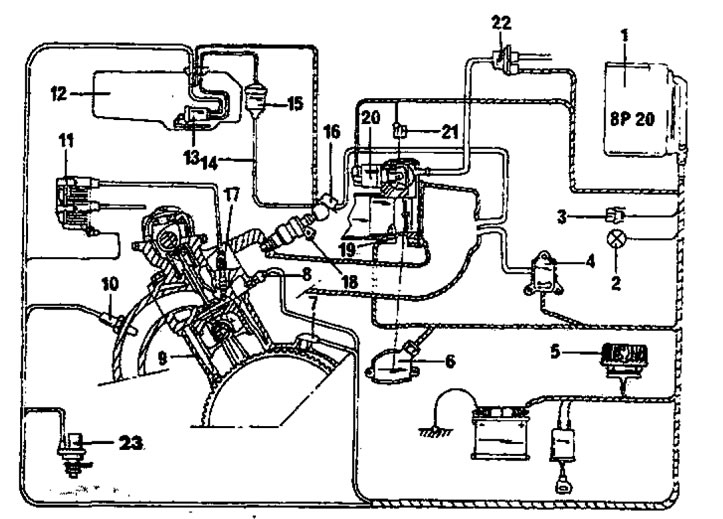
Figure 170. Functional diagram of the Magnetti Marelli fuel injection system. 1. Control unit; 2. Diagnostic system indicator lamp; 3. Diagnostic system connector; 4. Pressure sensor; 5. Duplicate relay(control unit / pump); 6. Throttle potentiometer; 7. Engine speed sensor (flywheel); 8. Temperature sensor; 9. Knock sensor; 10. Lambda probe; 11. Ignition coil; 12. Fuel tank; 13. Fuel pump (in the fuel tank); 14. Injection ring pipe; 15. Fuel filter; 16. Pressure regulator; 17. Spark plugs; 18. Injectors; 19. Air temperature sensor; 20. Idle speed control motor; 21. Idle circuit heater; 22. Electromagnetic valve of the activated carbon tank; 23. Speed sensor
The amount of fuel injected depends on the injector opening time. The injection duration depends on the engine load (pressure sensor) and engine speed (flywheel sensor).
Electronic components
At each engine revolution, all four injectors open simultaneously and fuel is injected into the intake manifold.
To compensate for the effects of different operating conditions, various corrections are made in the injection system.
The following factors influence the functioning of the system:
- Coolant temperature (temperature sensor).
- Operating conditions (idle speed. full load, transient, injection interruption).
- Atmospheric pressure.
- Battery voltage.
- Air density fluctuations (air temperature sensor).
- Information supplied by the lambda probe.
The control unit also regulates the following functions:
- As a result of evaluating the knock sensor data, the mixture composition is changed and the ignition timing is shifted to avoid overheating of the catalyst.
- Removal of gases (vapors) contained in a container with activated carbon into the intake system.
- Regulation of ignition timing and supply of additional air when the air conditioner is turned on.
- Operation of the diagnostic system indicator lamp.
- Engine protection against overspeeding due to interruptions in the ignition system (at 6500 rpm).
- Measuring the number of revolutions.
- Disconnection (and subsequent inclusion) injection at a speed of about 1400 rpm.
- Control of the idle speed control motor during the starting and idle phases.
The engine speed and dead center position sensor, located on the flywheel housing, has already been mentioned. Another sensor is used to determine the pressure in the engine. When the ignition is turned on before starting the engine, the sensor remembers the atmospheric pressure. This means that the sensor can transmit to the control unit all deviations from the atmospheric pressure in the intake manifold during engine operation. The sensor is supplied with 5 volts and produces a signal in the form of a voltage proportional to the pressure.
The throttle position sensor transmits information about the throttle position to the control unit. This information is used to determine the idle position (the gas pedal is released) and full load positions (the gas pedal is fully depressed). This is how control is achieved during acceleration, braking and injection interruptions.
The idle speed is controlled by the idle speed control motor. It is located in the throttle body and regulates the air supply by forcing air past the throttle valve. This ensures additional air supply when the engine is cold; idle speed is adjusted depending on the engine load and coolant temperature.
The coolant temperature sensor is located in the cooling system, the intake air temperature sensor is located in the air supply channel.
Air supply circuit
The air supply system is shown in Figure 171. Four cylinders are supplied with air through four intake ports with different cross-sections (progressively). The air supply is regulated by a single throttle valve.
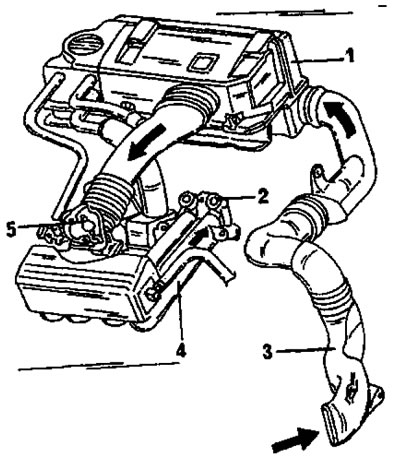
Figure 171. Schematic representation of the air supply system with the Magnetti Marelli device installed. 1. Air filter/Cylinder head cover; 2. Location of injectors; 3. Air supply channel; 4. Intake manifold; 5. Throttle body
The air filter is built into the compact engine and, in addition to filtering the supplied air, serves as a cylinder head cover, oil filler neck, oil separator from the engine crankcase vapors, and a spark plug wire mount. The filter element must be replaced every 30,000 km. Before removing the air filter, please read the instructions for removing and installing the cylinder head in the relevant section for XU engines).
[Source can be seen at PeugeotBook.ru]
A few words about the throttle body. The following parts are attached to it: a throttle cable, threaded fittings for connecting the fuel pressure regulator, a container with activated carbon, an engine pressure sensor, an additional air supply hose, a potentiometer, an electric heater, an air temperature sensor and an idle speed control motor.
Elements of the power supply system
In addition to the fuel tank, the following elements deserve special mention.
The fuel pump is installed horizontally in the fuel tank. The pump supplies fuel to the filter.
The fuel filter is mounted on the fuel tank and should be replaced every 30,000 km. The filter has an arrow that should point toward the front of the engine after installation.
Fuel vapors coming from the fuel tank are collected by passing through charcoal in a container with activated carbon. The switching valve connected to the tank is open in the off state. When the ignition is turned on, the valve closes. When the engine is running, the valve can open in response to signals from the control unit, that is, when pre-programmed conditions occur, and the fuel vapors in the tank are fed into the intake manifold for combustion. When the ignition is turned off, the valve remains closed for a few seconds to prevent the engine from running due to fuel vapors that may be coming from the tank.
The fuel pressure regulator is inserted into the fuel distribution pipe. Fuel is supplied to the regulator from the pump and the regulator maintains a constant fuel pressure of 2 bar in idle mode and 2.5 bar at full load. Unused fuel is returned back to the fuel tank.
The injectors spray fuel into the intake manifold. With each engine revolution, four injectors open.
Idle speed and CO content are not adjustable.
5.3.2 Fuel injection system Motronic MP 5.1
This system can be installed on 1.8-liter engines. However, these engines can also be equipped with the Magnetti Morelli system described above. This system is also installed on 1.6-liter engines. Like the Magnetti Morelli system described in Section 5.3.1, this system also responds to pressure and engine speed. Most of the elements already described are also present in this system, so there is no need to describe them.
Figure 172 shows the relative position of individual elements. As with the Magnetti Morelli system, the air filter is located on the inside of the cylinder head cover.
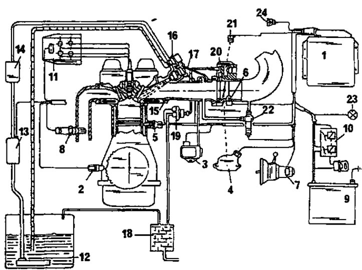
Figure 172. Functional diagram of the Motronic MP 5.1 fuel injection system. 1. Control unit; 2. Top dead center sensor (speed sensor); 3. Intake manifold pressure sensor; 4. Throttle potentiometer; 5. Coolant temperature sensor; 6. Intake air temperature sensor; 7. Speed sensor; 8. Lambda probe; 9. Battery; 10. Duplicate relay; 11. Ignition coil; 12. Fuel tank; 13. Fuel pump; 14. Fuel filter; 15. Fuel distribution pipe and intake manifold; 16. Pressure regulator; 17. Injectors; 18. Container with activated carbon; 19. Switching valve of the activated carbon tank; 20. Throttle body; 21. Throttle body heating sensor; 22. Idle air control valve; 23. Diagnostic system indicator lamp; 24. Diagnostic system connector
5.3.3 Bosch MP 3.2 fuel injection system
This system is installed on 16-valve engines. Many of the elements are consistent with the Magnetti Morelli system data, however there are some minor differences which are briefly described below. The functional diagram of this system is shown in Figure 173.
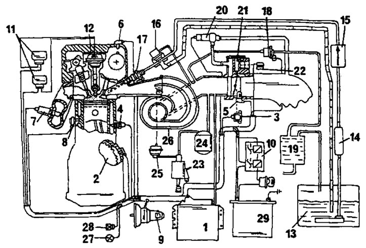
Figure 173. Functional diagram of the Sosch MP 3.2 system. 1. Control unit; 2. Speed sensor (at the flywheel); 3. Throttle potentiometer; 4. Coolant temperature sensor; 5. Intake manifold pressure sensor; 6. Cylinder ratio sensor; 7. Lambda probe; 8. Knock sensor; 9. Speed sensor; 10. Duplicate relay; 11. Ignition module; 12. Ignition coils; 13. Fuel tank; 14. Fuel pump; 15. Fuel filter; 16. Pressure regulator; 17. Injectors; 18. Switching valve of the activated carbon tank; 19. Container with activated carbon; 20. Idle air control valve; 21. Throttle body; 22. Throttle valve heating element; 23. Intake system electromagnetic valve; 24. Vacuum pump; 25. Pneumatic capsules of the intake system; 26. Intake manifold; 27. Diagnostic system indicator lamp; 28. Diagnostic system connector; 29. Battery
The injectors are inserted into the fuel distribution pipe and have separate control. Fuel is injected into one cylinder after another every two revolutions.
The fuel pressure regulator is inserted into the fuel distribution pipe and ensures constant pressure under all operating conditions (3 bar).
The air supply system of this engine has a special design. There is no need to go into details, but it should be noted that the intake manifold consists of two channels of different lengths and different cross-sections. The reason for installing such a system is to improve torque characteristics at low speeds.
The control unit switches off fuel injection in engine braking mode at speeds below 1280 rpm and resumes fuel supply when this speed is exceeded.
Overspeed protection disables fuel injection at 6840 rpm. The position sensor is mounted on the cylinder head.