



Table of contents: Removal 🠇 Installation 🠇
The necessary tools and equipment are shown in Figure 6.0.
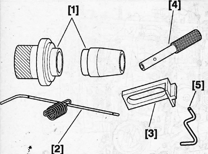
6.0. Tools and fixtures required for removing and installing camshafts 1 - set of mandrels for installing oil seals; 2 - thrust roller for fixing the flywheel of the DW12TED4 engine; 3 - flywheel fixing shoe; 4 - thrust roller for fixing the camshaft; 5 - thrust roller for fixing the crankshaft
Removal
1. Remove the air filter by disconnecting the air supply duct from the intake manifold.
2. Disconnect the crankcase ventilation hose and remove the cabin filter bracket and windshield wiper mechanism.
3. Remove the accessory drive V-belt, see the relevant chapter.
4. Remove the timing drive protective cover and timing belt, see the relevant chapter.
5. Cars with DW12TED4 engine. Unscrew the crankshaft position sensor and lock the shaft with stop 2 (see illustration).
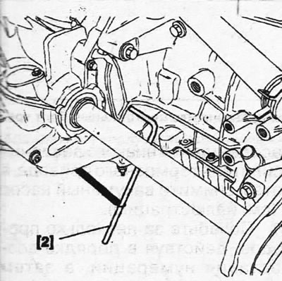
6.5. Unscrew the crankshaft position sensor and lock the shaft with stop 2. Cars with DW12TED4 engine
6. Cars with DW10ATED4 engine. Unscrew the crankshaft position sensor and lock the shaft with stop 5 (see illustration).
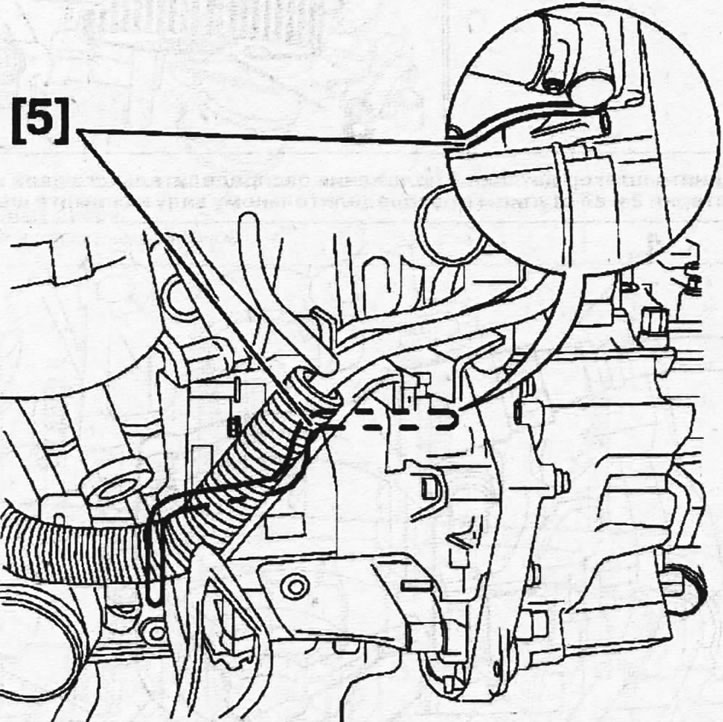
6.6. Unscrew the crankshaft position sensor and lock the shaft with stop 5. Cars with DW10ATED4 engine
7. Disconnect the high-pressure fuel lines and remove the fuel injectors together with the holders, see the relevant chapter.
8. Disconnect the plug of the camshaft position sensor 1 and remove the sensor, unscrew the central bolt securing gear 2 and its hub to the camshaft and remove the gear (see illustration).
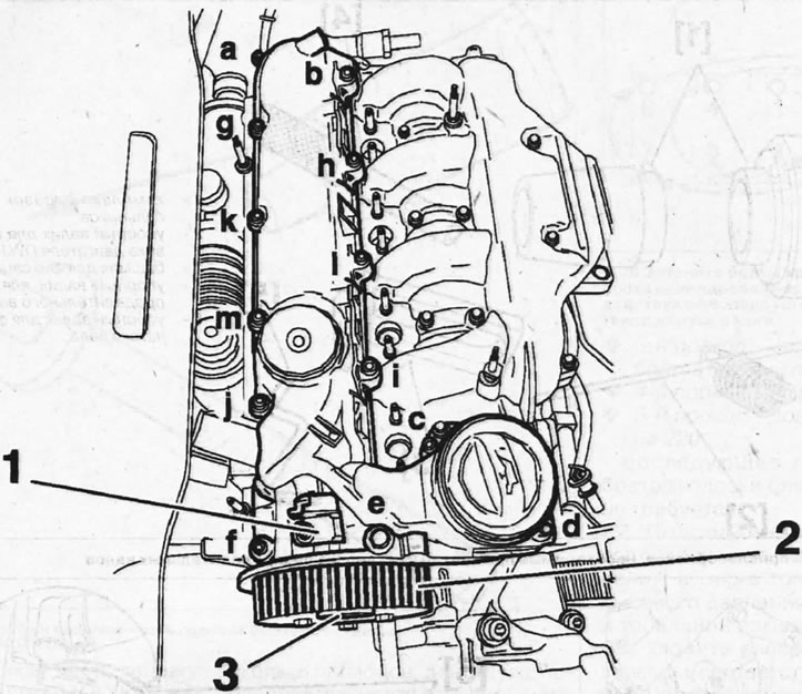
6.8. Disconnect the plug of the camshaft position sensor 1 and remove the sensor, unscrew the central bolt securing gear 2 and its hub to the camshaft and remove the gear
9. Unscrew the cylinder head cover mounting bolts in alphabetical order and remove the cover (see illustration 6.8).
10. Disconnect the brake booster low pressure hose 4 from the vacuum pump, and then remove the vacuum pump 5 (see illustration).
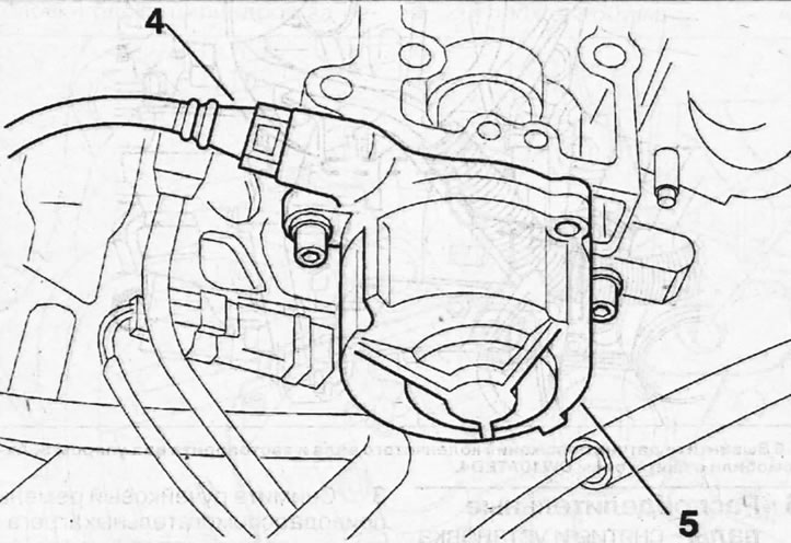
6.10. Disconnect the brake booster low pressure hose 4 from the vacuum pump, and then remove the vacuum pump 5
11. Loosen in several passes, acting in ascending order of numbering, and then unscrew the twenty-eight bolts securing the 6 camshaft bearing housings (see illustration 6.12).
12. Remove the 6 camshaft bearing housing, (see illustration).
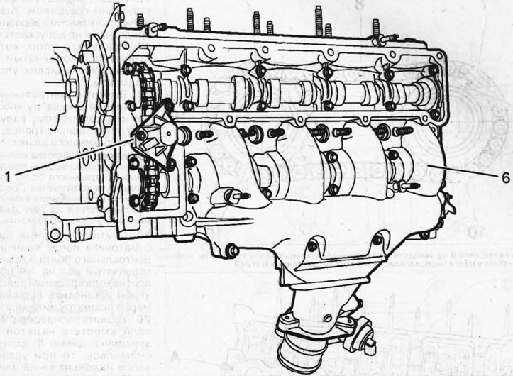
6.12. Remove the 6 camshaft bearing housing 1- tensioner of the intake camshaft drive chain
13. Remove tensioner 1 of the intake camshaft drive chain.
14. Remove hub 1 from the exhaust camshaft by unscrewing the central mounting bolt, if the hub was not removed together with the gear (see illustration).
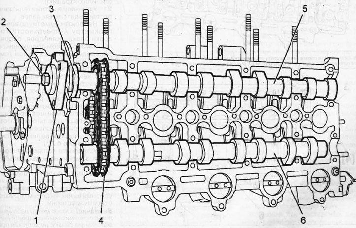
6.14. Remove hub 1 from the exhaust camshaft by unscrewing the central mounting bolt
15. Remove oil seal 3, then simultaneously remove both camshafts 5 and 6 together with chain 4 (see illustration 6.14).
Installation
16. Clean the mating surfaces of the cylinder head and bearing housing from any remaining sealing compound. It is recommended to use an appropriate cleaning agent for cleaning. Removal of the old sealant with abrasives is not permitted.
17. Remove the stop that was used to lock the crankshaft and lock the flywheel with a thrust shoe.
18. Screw in the central bolt securing the V-belt pulley to the crankshaft, if the bolt was not screwed in earlier after removing the belt pulley.
Caution! Do not block the crankshaft from turning when screwing in the central bolt with a thrust roller. Preventing the shaft from turning must be ensured by fixing the flywheel with a thrust shoe.
19. Remove the thrust shoe from the flywheel after screwing in the center bolt and turn the crankshaft 1/4 turn counterclockwise to position the pistons approximately in the center of the cylinders.
20. Place the camshafts together with the chain 8 put on their sprockets. If the chain was removed, then when installing the shafts, put it on the sprockets 10 so that the black chain links 7 are located opposite the timing marks 9 (see illustration).
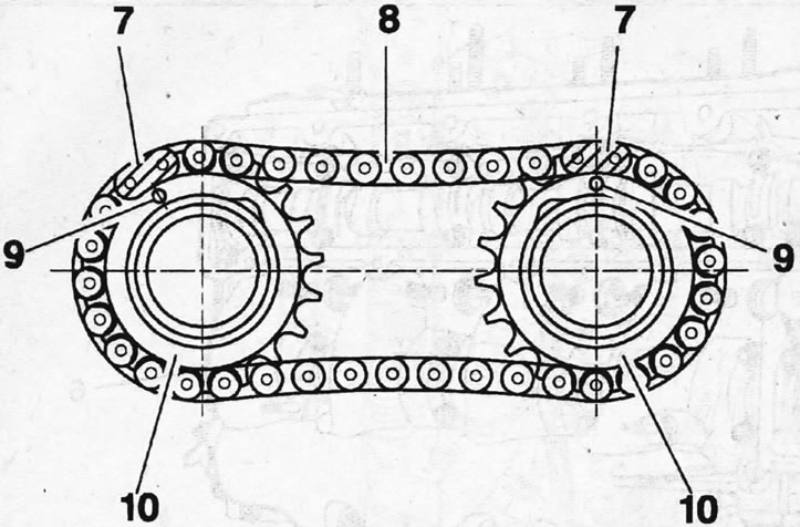
6.20. Place chain 8 on sprockets 10 of the camshafts so that the black chain links 7 are located opposite the timing marks 9
21. Install the camshaft chain tensioner.
22. Apply sealant around the entire perimeter of the A surface of the cylinder head that mates with the camshaft bearing housing (see illustration).
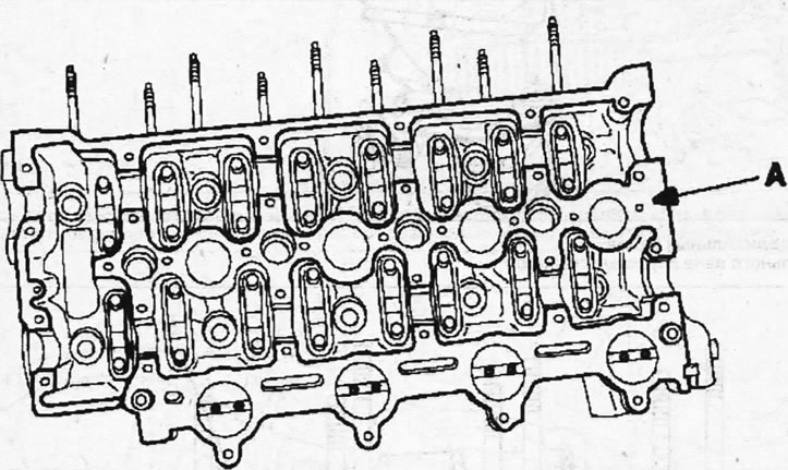
6.22. Apply sealant around the entire perimeter of the A surface of the cylinder head that mates with the camshaft bearing housing
23. Install bearing housing 6, screw in their mounting bolts and tighten them with a force of 10 Nm (see illustration).
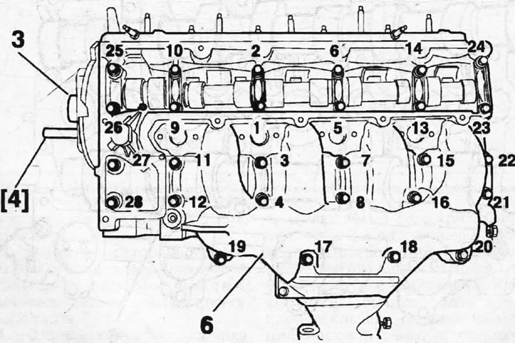
6.23. Install bearing housing 6, screw in their mounting bolts and tighten them with a force of 10 Nm
24. Install the hub 3 of the driven gear on the exhaust camshaft, secure it with the central bolt and lock the camshaft with the thrust roller 4 (see illustration 6.23).
25. Install the fuel injectors, replacing them with new threaded mounts.
26. Pack the intake camshaft oil seal. To do this, remove the thrust roller 4 and remove the gear hub from the shaft.
Caution! Apply universal grease to the gap between the seal's working surfaces, being careful not to allow any grease to come into contact with the seal's outer surface.
27. Place a new oil seal using an auxiliary sleeve on the projection of mandrel 1 and press it into place, igniting the mandrel with the central bolt of the gear (see illustration).
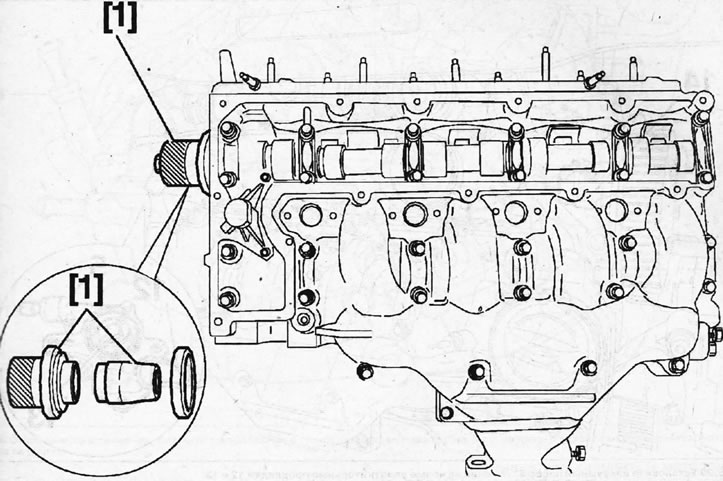
6.27. Place the new oil seal using the auxiliary sleeve on the projection of mandrel 1 and press it into place, pressing the mandrel with the central bolt of the gear
28. Install gear hub 3 on the exhaust camshaft, insert thrust roller 4, screw in and tighten bolt 11 with a force of 43 Nm (see illustration).
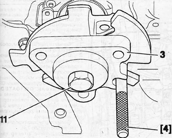
6.28. Install gear hub 1 on the exhaust camshaft, insert thrust roller 4, screw in and tighten bolt 11
29. Install vacuum pump 5, replacing with new sealing gaskets 12 and 13 (see illustration). Tighten the vacuum pump mounting bolts to 20 Nm.
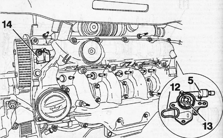
6.29. Install vacuum pump 5, replacing with new sealing gaskets 12 and 13
30. Install the cylinder head cover with its new sealing gasket, screw in and tighten the cover mounting bolts to 10 Nm.
31. Turn the crankshaft 1/4 turn and lock it with a stop.
32. Install the exhaust camshaft gear onto the hub.
33. Install the camshaft position sensor 14 and adjust the gap between the end of the sensor and the gear on the camshaft (see illustration 6.29). The gap should be 1.2 mm.
34. Install the timing belt and adjust its tension, see the relevant chapter.
Installation of all other removed components is carried out in the reverse order of removal.