



Removal
1. Jack up the car and place it on jack stands.
2. Remove the front wheel fender liners and engine compartment protection.
3. Disconnect both terminals from the battery terminals.
4. Drain the coolant and transmission oil.
5. Disconnect both drive shafts from the gearbox, see the relevant chapter.
6. Remove the windshield wiper mechanism and headlights.
7. Remove the front bumper, front cross member 1 and lower bumper cross member 2 (see illustration).
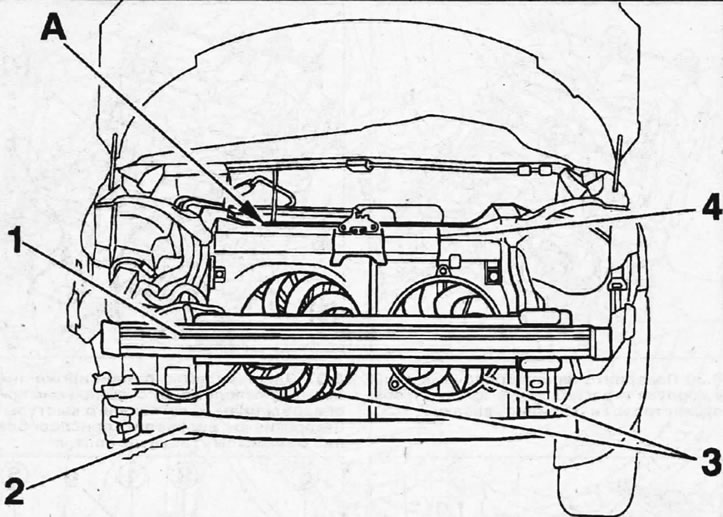
9.7. Remove the front bumper, front cross member 1 and bumper lower cross member 2
8. Disconnect the drive cable from the hood latch, release it from the holders and move it to the side.
9. Disconnect and move aside from the work area the transmission fluid cooling radiator, as well as the relay block A located in the engine compartment (see illustration 9.7).
10. Disconnect the plugs of the wires of the radiator fans 3 and move the wires to the side (see illustration 9.7).
11. Remove the coolant expansion tank and air filter.
12. Disconnect the A/C refrigerant pressure sensor, charge air cooler hoses, charge air pressure sensor, and lower and upper radiator hoses.
13. Remove the radiator, disconnect the air conditioning radiator from the upper cross member 4 of the front and move it to the side without disconnecting the refrigerant circulation lines from it.
14. All work related to disconnecting air conditioning pipes should be entrusted to a specialized workshop. Do not open the refrigerant circulation system yourself - there is a risk of frostbite!
15. Disconnect hose 5 from the heater radiator (see illustration).
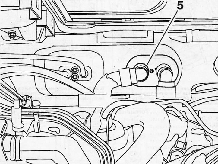
9.15. Disconnect hose 5 from the heater radiator
16. Disconnect and move aside the clutch slave cylinder, the ground (-) wire from the gearbox, and the low-pressure hoses.
17. Disconnect the reverse light sensor, fuel lines and release the engine wiring harness from the holders.
18. Disconnect the gear selection and shift cables from the gearbox.
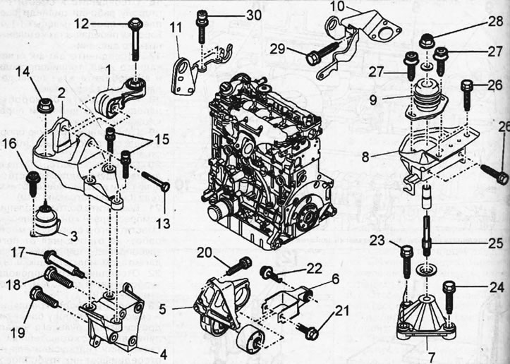
19. Disconnect the lower support 6 of the engine mount (see illustrations 9.19 and 9.0).
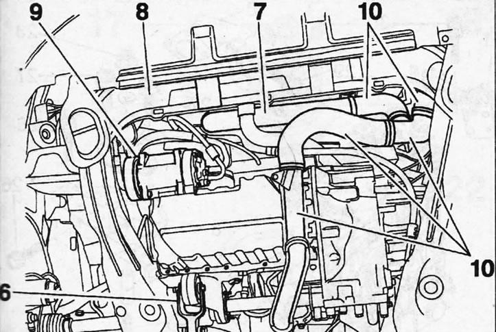
9.19. Disconnect the lower support 6 of the engine mount
9.0. Engine mounts and tightening torques 1 - jet thrust of the right support of the power unit; 2 - upper bracket of the right support of the power unit; 3 - right engine support; 4 - lower bracket of the right engine support; 5 - lower engine mount; 6 - lower support bracket; 7 - lower bracket of the left engine support; 8 - upper bracket of the left engine support; 9 - left engine support; 10 - left eye for lifting the engine; 11 - right eye for lifting the engine; 12 - bolt M10x150-75 with a non-falling washer for fastening the jet rod to the body. Tightening torque 50 Nm; 13 - bolt securing the rod to the bracket. Tightening torque 45 Nm; 14 - M10x150 nut for support pin. Tightening torque 45 Nm; 15 - three M10x150-60 bolts for fastening the upper bracket to the lower one. Tightening torque 60 Nm; 16 - two M8x125-25 bolts for mounting the support. Tightening torque 30 Nm; 17 - bolt M8x125-15 with a non-falling washer for fastening the lower bracket. Tightening torque 20 Nm; 18 - bolt M10x125-85. Tightening torque 45 Nm; 19 - two M10x125-70 bolts. Tightening torque 45 Nm; 20 - three M10x150-35 bolts for fastening the lower support. Tightening torque 45 Nm; 21 - bolt M10x150-72 with a non-falling washer of the lower support. Tightening torque 65 Nm; 22 - bolt M12x175-60 with a non-falling washer for fastening the lower support bracket. Tightening torque 90 Nm; 23 - nut M10x150 of bracket mounting bolt. Tightening torque 45 Nm; 24 - two bolts M10x150-5 bracket mount. Tightening torque 45 Nm; 25 - support finger. Tightening torque 50 Nm; 26 - four bolts M8x125-25 bracket mount. Tightening torque 25; 27 - two M8x125-25 bolts for fastening the support. Tightening torque 30 Nm; 28 - M12x175-15-18 nut of the support pin. Tightening torque 65 Nm; 29 - bolt M8x125-25 for fastening the eye. Tightening torque 15 Nm; 30 - two M6x100-20 bolts fastened to the eye. Tightening torque 12 Nm
20. Remove the radiator 7 for cooling the supercharged air together with the hoses and the fairing bracket 8 (see illustration 9.19).
21. Unscrew the mounting bolts of the air conditioner compressor 9 and move it away from the work area without disconnecting the refrigerant circulation pipes from it (see illustration 9.19).
22. Disconnect the turbocharger pipes 10 (see illustration 9.19).
23. Unscrew the mounting bolts and move the power steering reservoir together with the bracket, as well as the power steering pump, to the side, without disconnecting the pipes and hoses from them.
24. Remove the intake manifold and disconnect the exhaust pipe from the turbocharger.
25. Attach the hooks of a hoist or other lifting device to the engine eyes and lift the power unit slightly to relieve the load on the power unit suspension supports.
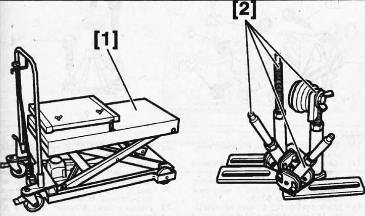
Attention! In workshops, a special lifting trolley is used for these purposes, which is installed under the power unit, and the power unit is secured to the trolley's supports (see illustration).
9.25. Lifting trolley 1 and supports 2 for fastening on the power unit trolley
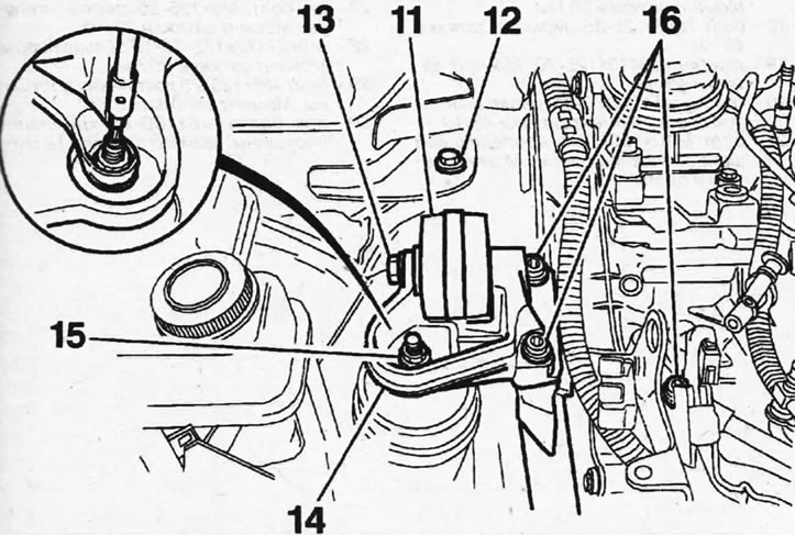
26. Unscrew 12 and 13 and disconnect the reaction rod 11 of the front engine mount support (see illustration 9.26 and 9.0).
9.26. Unscrew 12 and 13 and disconnect the reaction rod 11 of the front engine mount support
27. Unscrew nut 15, unscrew bolts 16 and disconnect the upper bracket 14 of the right support from the engine (see illustration 9.26 and 9.0).
28. Disconnect the left suspension support by unscrewing nut 17, unscrewing bolts 18 and removing support 19. After this, unscrew bolts 20 and 21 and disconnect the lower support bracket from the subframe (see illustration).
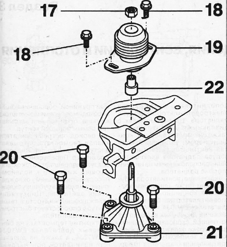
9.28. Disconnect the left suspension support by unscrewing nut 17, unscrewing bolts 18 and removing support 19
29. Disconnect the intermediate and lower brackets of the front support of the power unit (see illustration 9.0).
30. Make sure that all parts that impede removal of the engine are disconnected and removed.
31. Lower the power unit down and place it on a garage jack or other support and remove it from under the vehicle if not using a lifting dolly. If using a lifting trolley, lower it and remove the power unit attached to it.
Caution! Make sure the power unit does not come into contact with wires or pipes.
32. Place the power unit on suitable supports, such as wooden blocks, and secure it.
33. Inspect the power unit and make sure that it has no external damage or oil or coolant leaks.
34. Clean the engine surface. In this case, all parts that may be damaged during cleaning must be covered.
Important! It is recommended that engine rebuilds be performed by a specialized workshop, as this work requires specialized equipment and experience.
The engine is installed in the reverse order of removal.