



Table of contents: Removal 🠇 Installation 🠇
Balance shafts are installed on the DW12TED4 engine to dampen torsional vibrations. The shafts are installed in a housing, which is located in the oil pan and secured to the cylinder block.
Removal
1. Disconnect the negative (-) battery terminal from the battery.
2. Jack up the car and place it on jack stands.
3. Drain the engine oil.
4. Remove the accessory drive V-belt (see the corresponding operation).
5. Disconnect plugs 1 and 2 and disconnect crankcase ventilation hose 3 (see illustration).
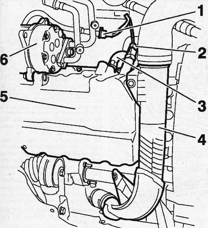
8.5. Disconnect plugs 1 and 2 and disconnect crankcase ventilation hose 3
6. Unscrew the air conditioning compressor mounting bolts and carefully move compressor 6 away from the work area without disconnecting the refrigerant circulation lines from it (see illustration 8.5).
7. Remove the dipstick guide tube.
8. Disconnect hose 4 and remove oil pan 5 (see illustration 8.5).
9. Unscrew the four bolts 7 and remove the oil pump 8 (see illustration).
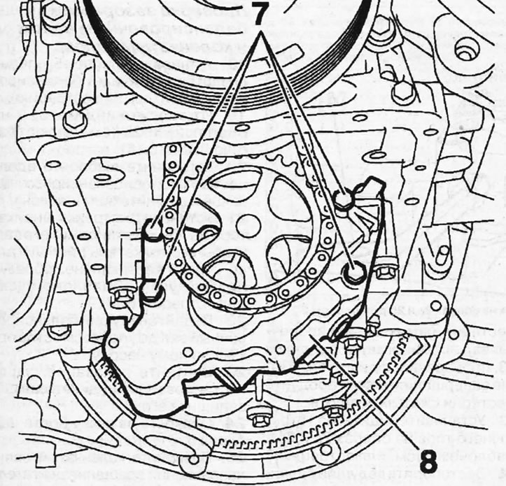
8.9 Unscrew the four bolts 7 and remove the oil pump 8
Attention! Mark the mounting position of bolts 7, as they have different lengths.
Checking the position of the balancing shafts
10. Lock the crankshaft with stop 3 (see illustration).
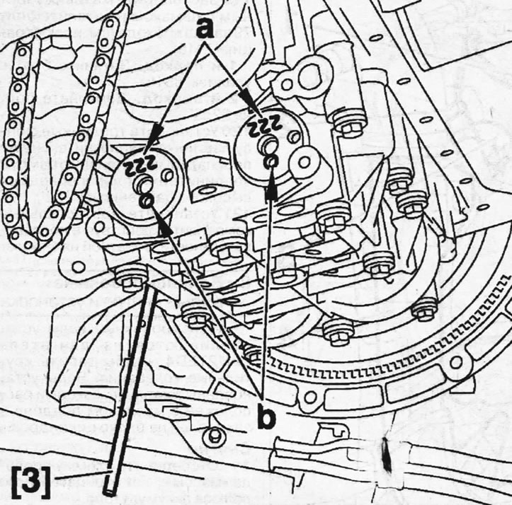
8.10. Lock the crankshaft with stop 3
11. Make sure that the 5mm diameter "b" holes are facing down and the "a" marks are facing up, towards the crankshaft (see illustration 8.10). Otherwise, the balance shafts must be removed, reinstalled and their position adjusted.
Checking the clearance between the balance shafts
12. Clean the ring gear of the crankshaft gear that drives the balance shafts, as well as the gears of the balance shafts themselves, by spraying them with D3 while cranking the engine. After cleaning is complete, blow out the gears with compressed air.
13. Install the arrow-type indicator 1 on supports 2a and 2b with template 5 (see illustration).
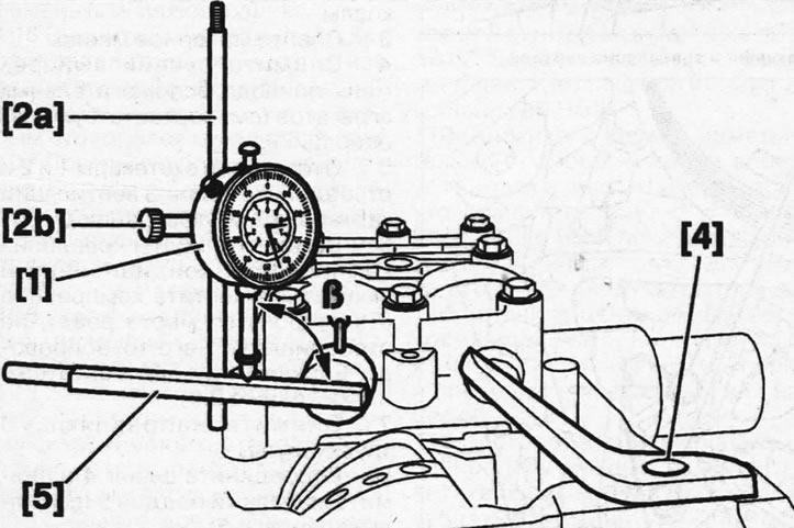
8.13. Install the arrow-type indicator 1 on supports 2a and 2b with template 5
14. Lock the main balance shaft with the stop lever 4 (see illustration 8.13).
15. Install template 5 on the driven balance shaft axis and secure with a bolt.
16. Set the indicator arrow to "0", turn the balancing shafts and determine the runout by the deflection of the indicator arrow. The nominal runout value of the balance shaft is 0.1-0.07 mm. If the runout does not match the specified value, the balance shaft housing should be replaced.
Caution! The measurement should be performed twice for every 180° of shaft rotation.
17. Remove all special tools.
Checking the clearance between the balance shaft and the crankshaft
18. Install template 5, resting its rod against the leading balancing shaft (see illustration).
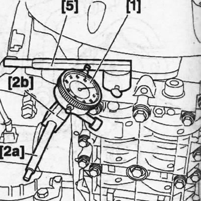
8.18. Install template 5, resting its rod against the leading balancing shaft
19. Install indicator 1 on supports 2a and 2b (see illustrations 8.13 and 8.18).
20. Install template 5 along the central axis of the balancing shafts and tighten the template bolt.
21. Set the indicator arrow to "0" and set it like this. so that its pusher is positioned strictly vertically, forming a right angle with the template (see illustration 8.13).
22. Feed the leading balance shaft until it stops, moving it towards the oil pump.
23. Read the reading recorded by indicator 1 and record it.
24. Loosen the template bolt 5.
25. Turn the crankshaft in the direction of engine rotation so that the balance shafts turn a quarter of a turn
26. Re-fasten template 5 with bolt.
27. Reset indicator 1. Again, push the balance shaft all the way towards the oil pump, read and record the indicator reading. Repeat this operation 7 times, turning the crankshaft one revolution.
The nominal clearance between the balance shaft and the crankshaft is 0.01-0.07 mm. If the clearance does not match the specified value, remove the balance shafts and measure their clearance.
28. Unscrew the eight bolts 9 and remove the housing 10 of the balancing shafts, as well as the adjusting linings (see illustration).
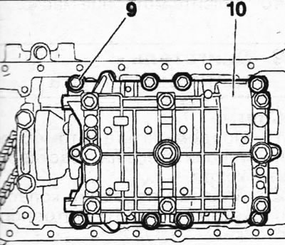
8.28. Unscrew the eight bolts 9 and remove the balance shaft housing 10
Installation
29. Inspect the balance shaft gear teeth and the crankshaft gears to ensure they are not worn or damaged.
30. Rotate the balance shafts in the housing and position them so that the holes "b" are at the top (see illustration).
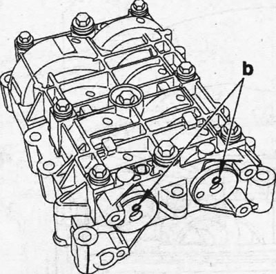
8.30. Turn the balance shafts in the housing and position them so that the holes "b" are at the top
31. Fix the balancing shafts in this position with special device 6, inserting its protrusions into holes "b", and secure device 6 with clamp 7, screwing in bolt "c" (see illustration).
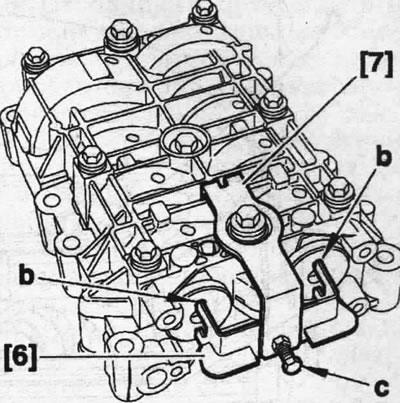
8.31. Fix the balancing shafts in this position with special device 6, inserting its protrusions into holes "b", and secure device 6 with clamp 7, screwing in bolt "c"
32. Place new 1.57 mm thick adjusting shims on the balance shaft housing.
Caution! Do not lubricate the adjusting linings.
33. Install the housing 10 of the balancing shafts onto its seat, secure with bolts 9 and remove the special device (see illustration).
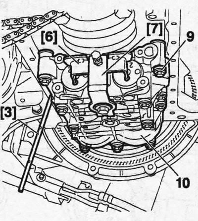
8.33. Install the housing 10 of the balancing shafts onto its mounting location, secure with bolts 9 and remove the special device
| Gap, mm | Thickness of the adjusting shim, mm |
| <0,05 | 1,57 |
| 0,05 | 1,51 |
| 0,06 | 1,49 |
| 0,07 | 1,47 |
| 0,08 | 1,47 |
| 0,09 | 1,45 |
| 0,10 | 1,43 |
| 0,11 | 1,41 |
| 0,12 | 1,41 |
| 0,13 | 1,39 |
| 0,14 | 1,37 |
| 0,15 | 1,35 |
| 0,16 | 1,35 |
| 0,17 | 1,33 |
| 0,18 | 1,31 |
| 0,19 | 1,29 |
| 0,20 | 1,29 |
| 0,21 | 1,27 |
| 0,22 | 1,25 |
| 0,23 | 1,23 |
| 0,24 | 1,23 |
| 0,25 | 1,21 |
| 0,26 | 1,19 |
| >0,26 | 1,19 |
[You can find the original on the page peugeotbook]
34. Tighten the eight bolts 9 to 22 Nm in ascending order of their numbering, then turn them an additional 60° (see illustration).
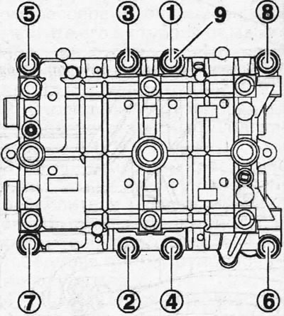
8.34. Tighten the eight bolts 9 to 22 Nm in ascending order of their numbering, and then turn them an additional 60°
The clearance between the balance shafts and the crankshaft can be adjusted using a suitable adjusting shim. The selection of the required gasket size depends on the size of the gap (see table).
Caution! If the gap is greater than 0.01 mm but less than 0.05 mm, select a 1.57 mm thick adjusting shim.
35. Install the oil pump 8, tighten the bolts 7 of its fastening, following the marks made during removal (see illustration 8.9).
36. Install the oil pan, dipstick guide tube and connect hose 4 (see illustration 8.5).
37. Install the air conditioning compressor on the support bracket.
38. Connect the crankcase ventilation hose.
39. Connect plugs 1 and 2 (see illustration 5.5).
40. Fill with engine oil.