



Table of contents: Removal 🠇 Installation 🠇
To remove and install the timing belt, the following tools and equipment are required: (see illustration 4.0).
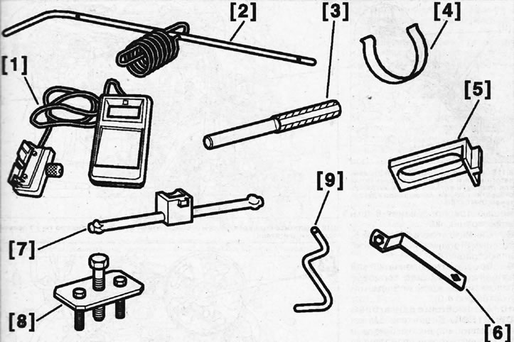
4.0. Tools and devices for removing and installing a timing belt 1 - device for measuring the tension of a toothed belt; 2 - device for fixing the crankshaft of the DW12TED4 engine; 3 - camshaft thrust roller; 4 - clamping the toothed belt when laying it on the drive gear; 5 - thrust shoe for fixing the flywheel; 6 - key for turning the crankshaft by the central bolt; 7 - key for the eccentric roller of the toothed belt tensioner; 8 - device for removing the V-belt pulley from the crankshaft; 9 - stop for fixing the crankshaft of the DW10ATED4 engine
Removal
1. Remove the right front wheel.
2. Remove the mudguard and engine protective cover.
3. Remove the accessory drive V-belt, see the relevant chapter.
4. Unscrew the mounting bolts and remove the clutch cover, see the relevant chapter.
5. Lock the flywheel with the thrust shoe 5 (see illustration).
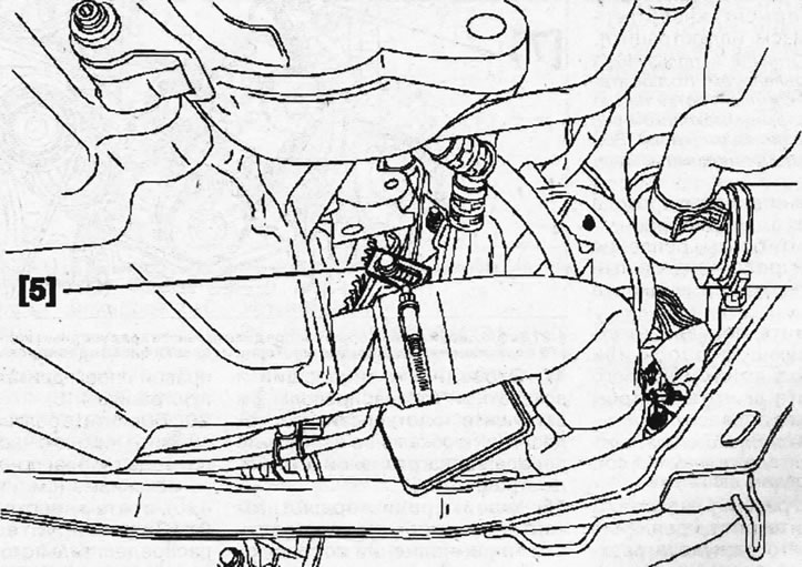
4.5. Lock the flywheel with the thrust shoe 5
6. Unscrew the central bolt securing the V-belt pulley to the crankshaft, remove the washer from the bolt and screw the bolt back in.
7. Remove the V-belt pulley from the crankshaft using tool 8 (see illustration 4.0).
8. Remove the thrust shoe 5 that held the flywheel in place(see illustration 4.5).
9. Turn the crankshaft by the central bolt with a socket head or a 6 key (see illustration 4.0).
10. Cars with DW12TED4 engine. Unscrew the crankshaft position sensor and lock the crankshaft with stop 2, inserting it into the sensor mounting hole (see illustration 4.0).
11. Cars with DW10ATED4 engine. Unscrew the crankshaft position sensor and lock the crankshaft with stop 9, inserting it into the sensor mounting hole (see illustration).
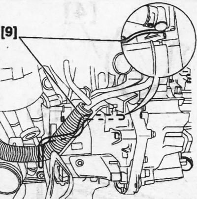
4.11. Unscrew the crankshaft position sensor and lock the crankshaft with stop 9, inserting it into the sensor mounting hole. Cars with DW10ATED4 engine
Please note: The difference in thrust bearings used is due to the fact that DW12TED4 engines are equipped with a composite flywheel, while DW10ATED4 engines use a traditional solid flywheel.
12. Disconnect the negative (-) battery terminal.
13. Unscrew the mounting bolts and move the coolant expansion tank to the side.
14. Place a suitable support or garage lift under the engine and raise the engine slightly to relieve the load on its suspension.
Caution: Place a wooden block on the support or lift rod to prevent damage to the engine.
15. Remove the radiator grille.
16. Unscrew the mounting bolt and disconnect the reaction rod 1 of the right engine mount from the body (see illustration).
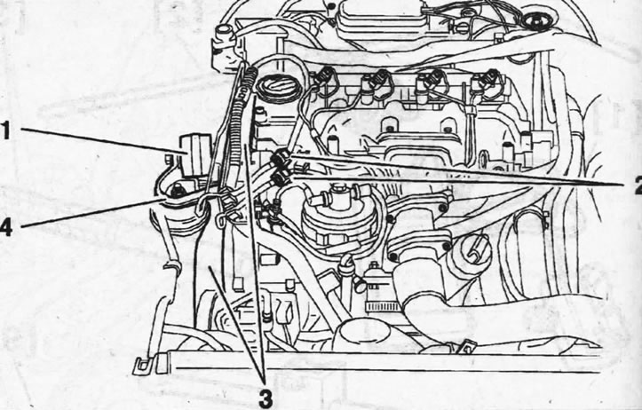
4.16. Unscrew the mounting bolt and disconnect the reaction rod 1 of the right engine mount from the body
17. Disconnect the supply and return fuel lines 2 and seal their openings with suitable plugs to prevent contamination from entering (see illustration 4.16).
18. Cover the radiator with thick cardboard to avoid damage during subsequent work.
19. Disconnect bracket 4 of the right engine support (see illustration 4.16).
20. Unscrew the mounting bolts and remove the lower part 3 of the timing cover (see illustration 4.16), and then the top one.
21. Fix the camshaft gear with thrust roller 3, inserting it into the aligned holes of the gear and the cylinder head (see illustration).
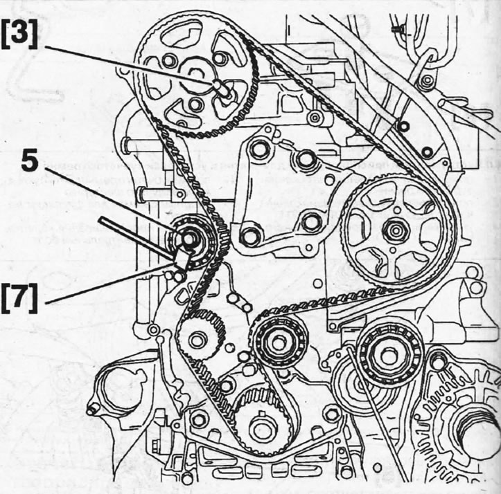
4.21. Fix the camshaft gear with thrust roller 3, inserting it into the aligned holes of the gear and the cylinder head
22. Loosen bolt 5, which secures the toothed belt tension roller, and then turn the roller eccentric with key 7 clockwise to loosen the toothed belt tension as much as possible, and secure the roller in this position by tightening bolt 5 (see illustration 4.21).
23. Remove the timing belt.
Installation
24. Check the condition of the timing belt to draw conclusions about the condition of the timing drive components.
25. Check the movement of the timing belt tension roller and guide rollers and make sure that they do not make noise.
26. Check for any signs of oil leaks on the crankshaft and camshaft seals.
27. Inspect the surfaces around the water pump and ensure there are no coolant leaks.
28. Replace damaged or worn parts with new ones.
29. Place the timing belt on the crankshaft gear and secure it with a special clamp 4 (see illustrations 4.0 and 4.30).
30. Place the toothed belt on the guide roller 6, gear 10 of the fuel injection pump, gear of the camshaft, gear 7 of the water pump and tension roller 5 (see illustration).
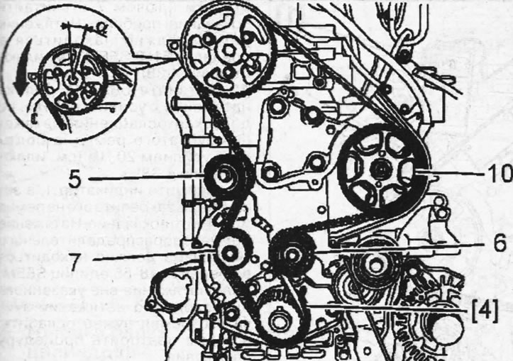
4.30. Place the toothed belt on the guide roller 6, gear 10 of the high-pressure fuel pump, gear of the camshaft, gear 7 of the water pump and tension roller 5
Attention! If necessary, the camshaft gear can be moved counterclockwise on the hub by loosening the tightening of bolts 8 (see illustration 4.32). The offset angle should not exceed one belt tooth (see illustration 4.30)
31. Remove clamp 4, which held the toothed belt on the crankshaft drive gear.
32. Loosen bolt 11 of the tension roller, turn its eccentric with key 7 counterclockwise, tensioning the toothed belt. While holding the roller eccentric in this position, tighten the tension roller bolt 11 (see illustration).
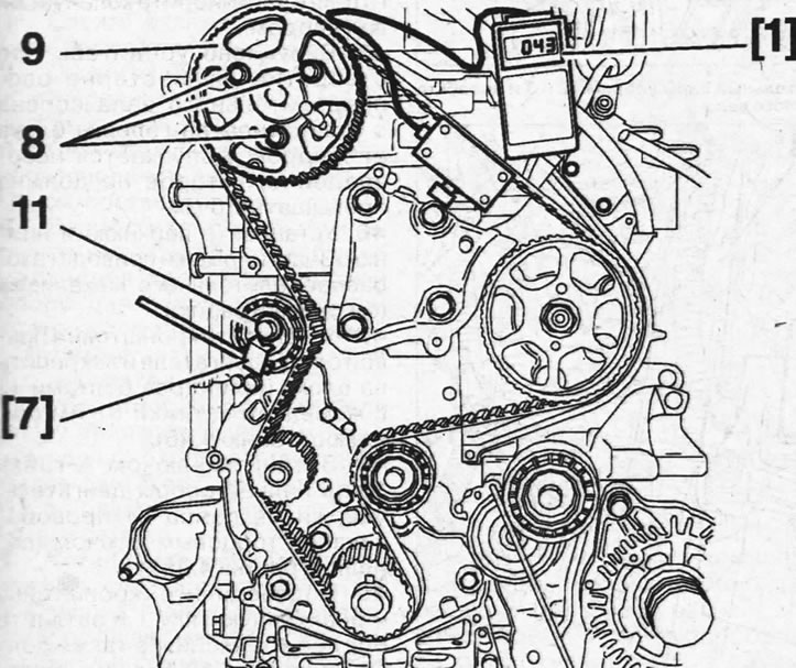
4.32. Loosen the tension roller bolt 11, turn its eccentric with key 7 counterclockwise, tensioning the toothed belt
Checking the timing belt tension
33. Check the tension of the timing belt with indicator 1, having secured its sensor to the belt at the section between the fuel injection pump gear and the camshaft (see illustration 4.32).
34. Loosen the tightening of the tension roller bolt 11 and turn the roller counterclockwise with the key 7 until the belt tension indicator registers 98?2 SEEM (see illustration 4.32).
35. Tighten tension roller bolt 11 to 25 Nm, maintaining the specified belt tension (see illustration 4.32).
Caution! If the camshaft gear bolts 8 were loosened to allow it to move on the hub, tighten them to 20 Nm (see illustration 4.32). When doing this, make sure that the bolts are approximately in the center of the elongated holes on the gear, and do not rest against their ends.
36. Remove all stops and special devices, and also remove device 1 from the belt, which was used to check its tension.
37. Turn the crankshaft eight revolutions in the direction of engine rotation.
Caution! Do not turn the engine in the direction opposite to its rotation.
38. Lock the crankshaft and camshaft with stops 2 and 3 and loosen the tightening of bolts 8 of the camshaft gear so that the gear can be turned on the hub (see illustration).
The source is located on the website peugeotbook.ru
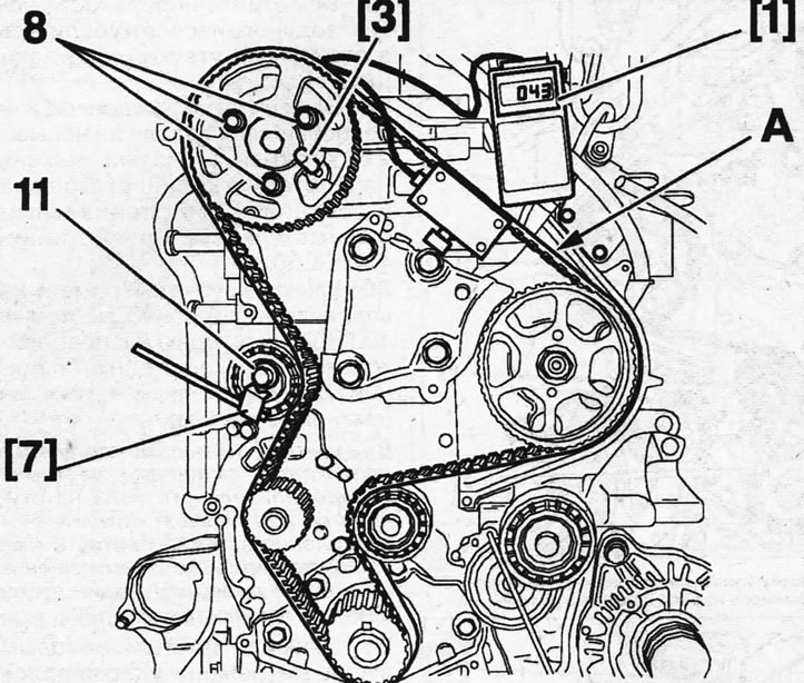
4.38 Lock the crankshaft and camshaft with stops 2 and 3 and loosen the tightening of bolts 8 of the camshaft gear
39. Loosen the tightening of bolt 11 securing the toothed belt tension roller (see illustration 4.38).
40. Secure the belt tension indicator sensor 1 to the section between the injection pump gear and the camshaft (see illustration 4.38).
41. Turn the tension roller eccentric counterclockwise with key 7 and read the instrument reading. The belt tension should be within 51±2 SEEM (see illustration 4.38).
42. Tighten bolt 11 of the tension roller with a force of 25 Nm, without allowing the toothed belt tension to loosen, and bolts 8 with a force of 20 Nm (see illustration 4.38).
43. Remove indicator 1, then reattach it to the belt and read the reading. The timing belt tension should be between 48 and 55 SEEM. If the tension is outside this range, loosen the timing belt tension and then repeat the tensioning procedure.
44. Turn the crankshaft twice in the direction of engine rotation and lock the crankshaft with a stop.
45. Visually check that the hole on the camshaft gear is aligned with the hole on the cylinder head. A discrepancy of no more than 1.0 mm is allowed.
46. Install the upper and lower 3 parts of the timing cover (see illustration).
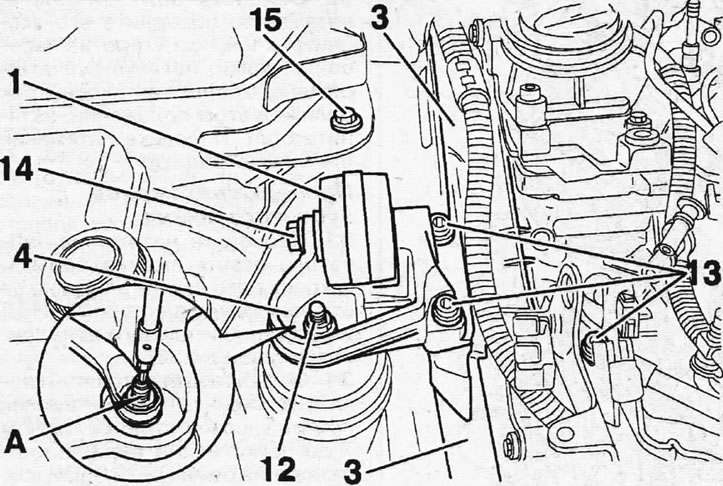
4.46 Install the lower 3 part of the timing cover
47. Install bracket 4 of the right engine support and secure it to the cylinder block with bolts 13 with a tightening torque of 61 Nm (see illustration 4.46).
48. Tighten nut 12 on the engine mount pin with wrench A, holding the pin from turning with a socket wrench (see illustration 4.46).
49. Connect the reaction rod 1 to the bracket 4 and tighten its mounting bolt, as well as bolt 15 with a force of 50 Nm (see illustration 4.46).
50. Lock the flywheel with a thrust shoe, install the V-belt pulley on the crankshaft and screw in the central mounting bolt, lubricating its threads with Loctite Frenetanch sealant.
51. Tighten the center bolt to 70 Nm, then turn it a further 60° to ensure the final tightening torque of the bolt is 260 Nm.
52. Place the V-belt and install all other components.