



Table of contents: Disassembly 🠇 Assembly 🠇
Important! Disassembly and assembly instructions are shown using the DW10ATED engine as an example. Differences between the DW10ATED4 and DW12TED4 engines are provided in the text.
Disassembly
1. Remove the engine, see the relevant chapter.
2. Disconnect the plugs of the sensors and valves on the engine, release the wires from the holders and remove them.
3. Remove the EGR solenoid valve.
4. DW10ATED engine. Unscrew the mounting bolts and remove the exhaust manifold 1 together with the turbocharger 3 and sealing gaskets (see illustration).
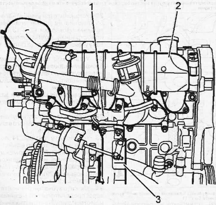
7.4. Remove the exhaust manifold 1 together with the turbocharger 3 and sealing gaskets
5. Remove the intake manifold 2 (see illustration 7.4).
6. Disconnect plug "a", remove bracket 4, as well as guide tube 9 of the engine oil level indicator rod (dipstick) (see illustration).
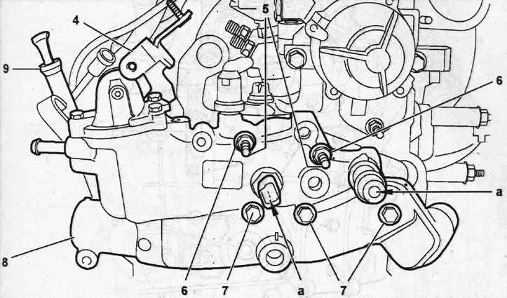
7.6. Disconnect plug "a", remove bracket 4, as well as guide tube 9 of the engine oil level indicator rod (dipstick)
7. Unscrew nuts 6, and then unscrew studs 5 by locking two nuts onto them (see illustration 7.6).
8. Unscrew bolts 7 and remove thermostat housing 8 with outlet pipe (see illustration 7.6).
9. Drain the condensate and any fuel in the fuel filter into a suitable container by unscrewing the drain plug 11 (see illustration).
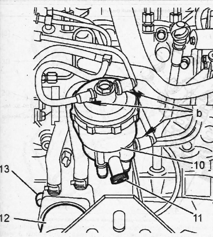
7.9. Drain the condensate and any fuel in the fuel filter by unscrewing the drain plug 11
10. Clean the connecting joints "b" of the fuel lines on the fuel filter 10 and disconnect them (see illustration 7.9). Seal the fuel line openings with suitable plugs.
11. Remove the fuel filter 10 (see illustration 7.9).
12. Disconnect the oil filter 12 and the engine oil cooling radiator 13 (see illustration 7.9).
13. Remove the generator and unscrew the pipe 16 on which the oil filter is attached (see illustrations 7.13, 7.13a).
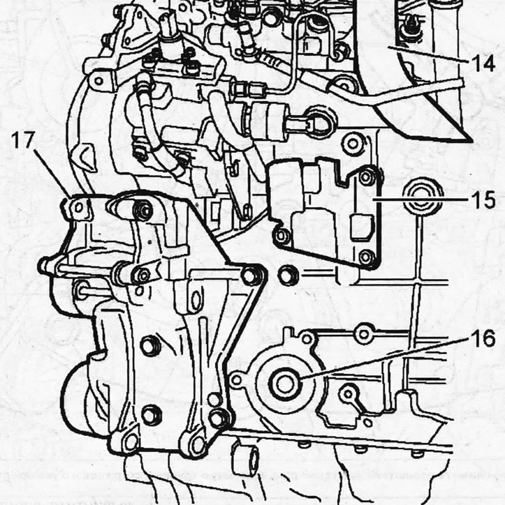
7.13. Remove the generator and unscrew the pipe 16 on which the oil filter is attached
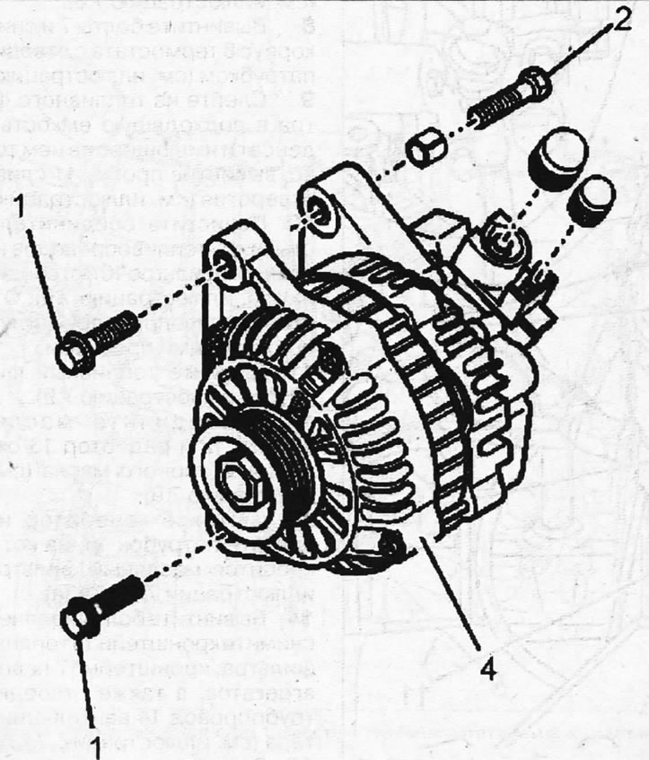
7.13a. Valeo Generator 1 - mounting bolts M10x150-50. Tightening torque 41 Nm; 2 - mounting bolt M10x150-40. Tightening torque 39 Nm; 4 - generator
14. Unscrew the mounting bolts and remove the fuel filter bracket 15, the bracket 17 of the attachments, and also disconnect the crankcase ventilation pipe 14 (see illustration 7.13).
15. Lock the flywheel with a stop shoe, unscrew the central bolt of the belt pulley 20 and remove the pulley from the crankshaft (see illustration).
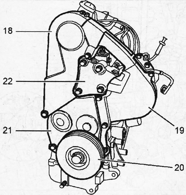
7.15. Lock the flywheel with a thrust shoe, unscrew the central bolt of the belt pulley 20 and remove the pulley from the crankshaft
16. Unscrew the mounting bolts and remove both upper 18 and 19 and lower 21 parts of the timing cover (see illustration 7.15).
17. Disconnect the upper bracket 22 of the right engine mount support (see illustration 7.15).
18. Unscrew the mounting bolts and remove the starter, and also remove the thrust shoe that held the flywheel in place.
19. Unscrew the crankshaft position sensor and lock the crankshaft with stop 13, inserting it into the sensor hole (see illustration, part A).
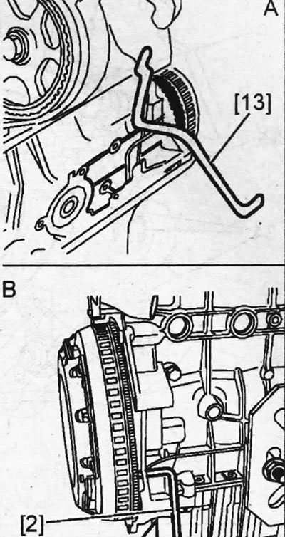
7.19. Unscrew the crankshaft position sensor and lock the crankshaft with stop 13, inserting it into the sensor hole
20. If the engine is equipped with a so-called composite flywheel, rather than a solid flywheel, then a thrust roller 2 is used to lock the crankshaft (see part B in illustration 7.19).
21. Lock the camshaft with the thrust roller 3 (see illustration).
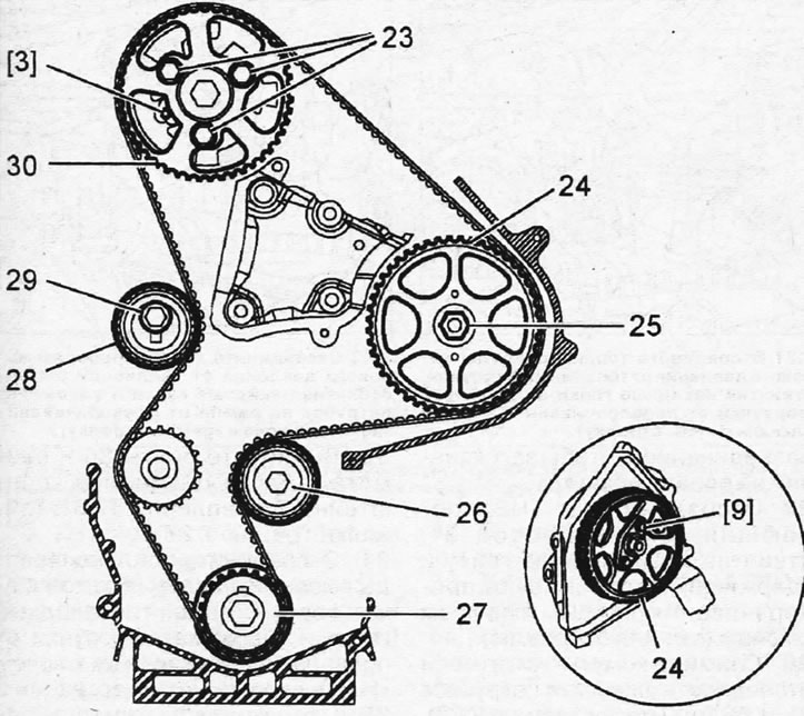
7.21. Lock the camshaft with thrust roller 3
22. Loosen the tightening of bolt 29 securing tension roller 28 of the timing belt, turn the roller to loosen the belt tension, and remove the timing belt (see illustration 7.21).
23. Unscrew bolts 23 securing gear 30 of the camshaft to the hub and remove the gear (see illustration 7.21).
24. Remove the guide roller 26, tension roller 28, and also the drive gear 27, held on the crankshaft by a key (see illustration 7.21). Remove the key from the groove so that it does not get lost during disassembly.
25. Unscrew nut 25 securing gear 24 to the injection pump shaft, holding the gear from turning with a suitable stop, and remove the gear using tool 9, screwing two bolts of the tool into the holes on the gear(see illustration 7.21).
26. Clean the fuel line connections before disconnecting them to prevent contamination from getting inside.
27. Disconnect the fuel supply line 31 from the high-pressure fuel pump by unscrewing its union nut and holding the pipe "d" from turning with a second wrench (see illustration).
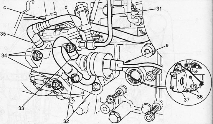
7.27. Disconnect the fuel supply line 31 from the high-pressure fuel pump by unscrewing its union nut and holding the branch pipe "d" from turning with a second wrench
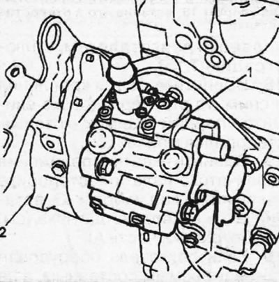
7.27a High-pressure fuel pump 1 and its support bracket 2
28. Remove clamps "c" and "e" and disconnect the hoses from pipes 33 and 35 (see illustration 7.27). Seal the pipe openings with plugs.
29. Unscrew bolts 32 and 34 and remove the high pressure fuel pump (see illustrations 7.27, 7.27a).
30. Unscrew bolts 36 and remove the fuel injection pump mounting bracket 37 from the cylinder block (see illustration 7.27).
31. Disconnect the high pressure fuel lines from the fuel injectors by unscrewing the union nuts and holding the injectors from turning with an "f" spanner (see arrow in illustration).
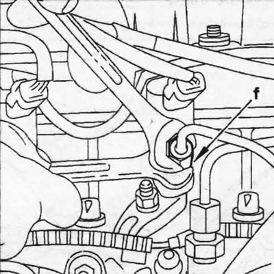
7.31. Disconnect the high-pressure fuel lines from the fuel injectors by unscrewing the union nuts and holding the injectors from turning with a spanner "f" (see arrow)
32. Disconnect the high-pressure fuel lines from the fuel rail by unscrewing the union nuts and holding the pipe on the rail from turning with a "g" spanner (see arrow in illustration).
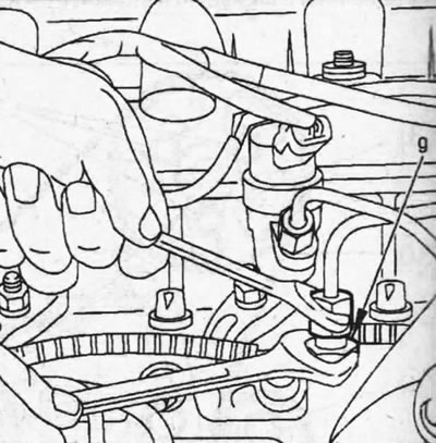
7.32. Disconnect the high-pressure fuel lines from the fuel rail by unscrewing the union nuts and holding the pipe on the rail from turning with a "g" spanner (see arrow)
33. Disconnect the return fuel lines from the fuel injectors 38 (see illustration).
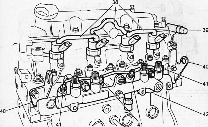
7.33. Disconnect the return fuel lines from the fuel injectors 38
34. Unscrew the mounting bolts and remove the fuel rail 42 (see illustration 7.33).
35. Cars with DW10ATED engine. Unscrew glow plugs 41 (see illustration 7.33).
36. Disconnect the lugs 40 for lifting the engine by unscrewing the mounting bolts (see illustration 7.33).
37. Remove the vacuum pump 39 (see illustration 7.33).
38. Engine DW10ATED4. Remove fuel injectors 55 by placing special tools 7 on nuts 54 of the injector holder, which should go under the edge "k" of the nut on the injector. After this, unscrew the nuts 55 of the injector holder (see illustrations 7.38, 7.38a, 7.38b).
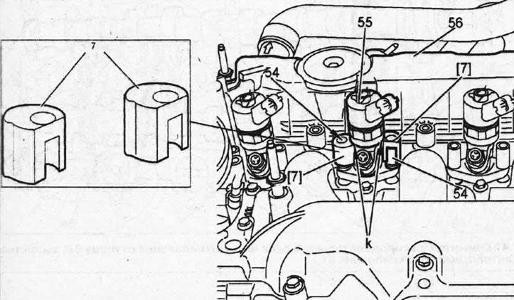
7.38. Place special tools 7 on the nuts 54 of the injector holder, which should go under the edge "k" of the nut on the injector, and unscrew the nuts. DW10ATED4 engine
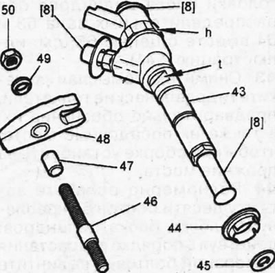
7.38a. Fuel injector 43 and its mount on the DW10ATED engine 50 - holder nut; 49 - gasket; 48 - nozzle holder; 47 - bushing; 46 - hairpin; 45 - copper sealing ring; 44 - centering sleeve
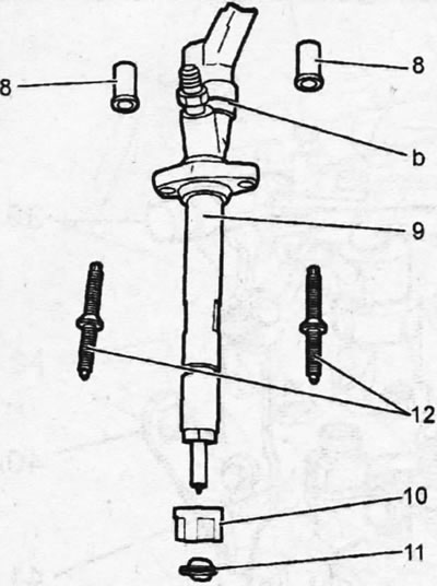
7.38b. Fuel injector 9 and its mount on the DW10ATED4 engine 8 - fastening nuts; 10 - seal; 11 - copper sealing ring; 12 - hairpins
Caution! Do not remove the injector by nut "b".
39. Engine DW10ATED4.
Unscrew the mounting bolts and remove the cylinder head cover 56 (see illustration 7.38).
40. Engine DW10ATED4. Unscrew eight studs 58 and twenty-eight bolts 57, remove the camshaft bearing housing 59 and the camshaft chain tensioner 60 (see illustration).
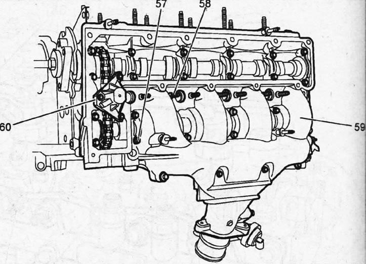
7.40. Unscrew eight studs 58 and twenty-eight bolts 57, remove the camshaft bearing housing 59 and the camshaft chain tensioner 60. DW10ATED4 engine
41. Remove the hub 66 from the intake camshaft by unscrewing the central mounting bolt 61 (see illustration).
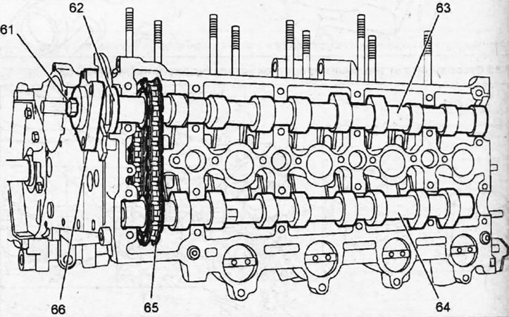
7.41. Remove the hub 66 from the intake camshaft by unscrewing the central mounting bolt 61
42. Remove oil seal 62, then simultaneously remove both camshafts 63 and 64 from the cylinder head together with chain 65 (see illustration 7.41).
43. Remove the rocker arms and take out the hydraulic tappets, having first marked them and their mounting locations so that they can be installed in their original locations during assembly.
44. Evenly loosen the ten cylinder head mounting bolts 67, acting in ascending order of the bolt numbering, and unscrew them (see illustration).
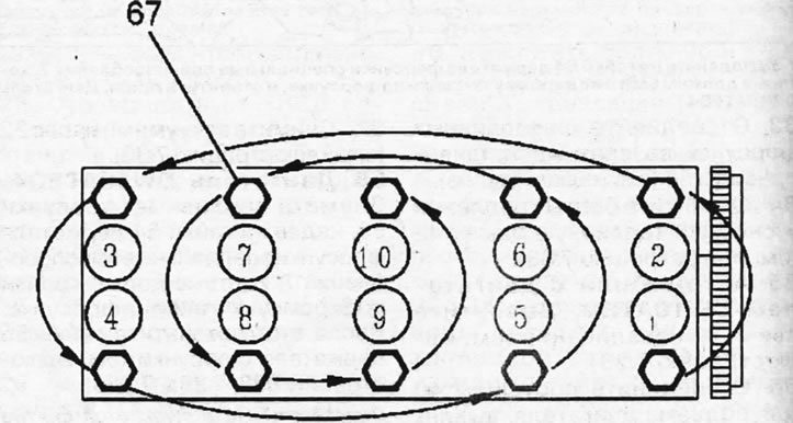
7.44. Loosen the ten cylinder head mounting bolts 67, acting in ascending order of the bolt numbering, and unscrew them
45. Remove the head and its sealing gasket from the cylinder block using special levers.
46. Lock the flywheel with the thrust shoe 1 (see illustration).
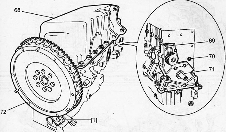
7.46. Lock the flywheel with thrust shoe 1. The illustration shows the flywheel after removing the clutch
47. Unscrew the mounting bolts and remove the pressure and driven clutch discs, see the relevant chapter.
48. Unscrew the mounting bolts and remove the flywheel 72 and oil pan 68 (see illustration 7.46).
49. Unscrew the mounting bolts 69 and remove the water pump and the oil pump cover 71 with the crankshaft oil seal, as well as the oil channel plug 70 (see illustration 7.46).
50. Disconnect the engine oil level indicator tube 74, unscrew the oil pump mounting bolts 73, marking them (see illustration).
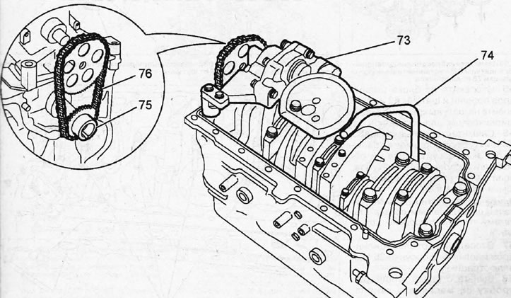
7.50. Disconnect the engine oil level indicator tube 74 and unscrew the oil pump mounting bolts 73
51. Remove the oil pump drive chain 76 from the sprockets, the oil pump 73, and then the sprocket 75 from the crankshaft (see illustration 7.50).
52. Unscrew the nuts and remove the 78 connecting rod bearing caps (see illustration).
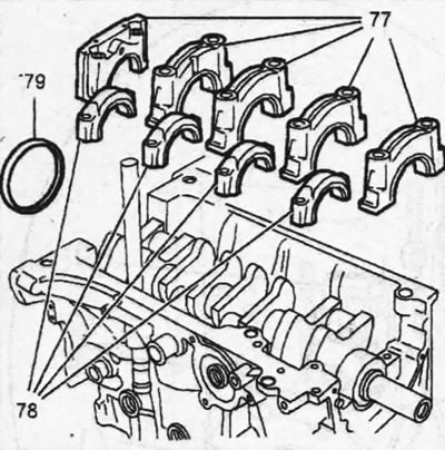
7.52. Unscrew the nuts and remove the 78 connecting rod bearing caps
53. Unscrew the bolts and remove the main bearing caps 77, as well as the crankshaft oil seal 79 (see illustration 7.52).
54. Remove the crankshaft 81, mark and remove the liners, as well as the thrust half rings 80 (see illustration).
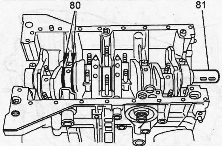
7.54. Remove crankshaft 81, mark and remove liners, as well as thrust half rings 80
55. Remove the pistons and connecting rods 82 from the cylinder block and install the bearing caps 78 on the connecting rods (see illustration).
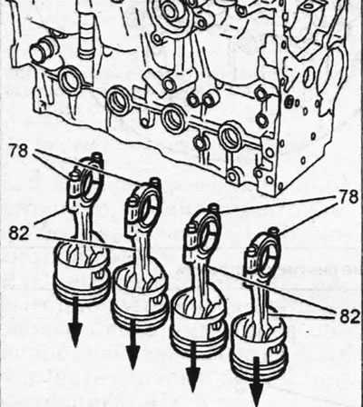
7.55. Remove the pistons and connecting rods 82 from the cylinder block and install the bearing caps 78 on the connecting rods
56. Remove the retaining rings 3 on both sides of the piston pin 85, press out the pin and disconnect the pistons 84 from the connecting rods, if necessary (see illustration).
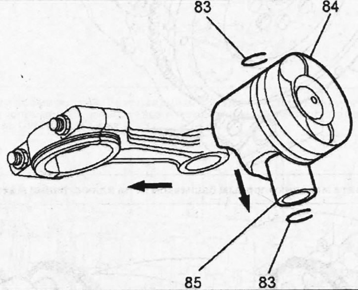
7.56. Remove retaining rings 83 from both sides of piston pin 85, press out the pin and disconnect pistons 84 from the connecting rods
Caution! Pistons and connecting rods must be marked before separation, as they are matched to each other.
57. Disconnect the oil injectors 86 from the cylinder block (see illustration).
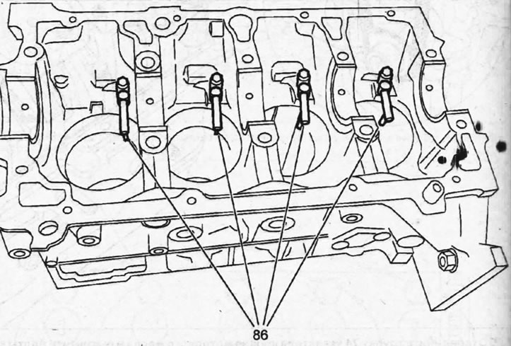
7.57. Disconnect the oil injectors 86 from the cylinder block
58. Remove the oil channel plug 88 from the cylinder block, disconnect the engine oil level sensor 87 and the engine oil pressure sensor 89 (see illustration).
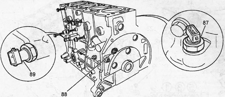
7.58. Remove the oil channel plug 88 from the cylinder block, disconnect the engine oil level sensor 87 and the engine oil pressure sensor 89
Assembly
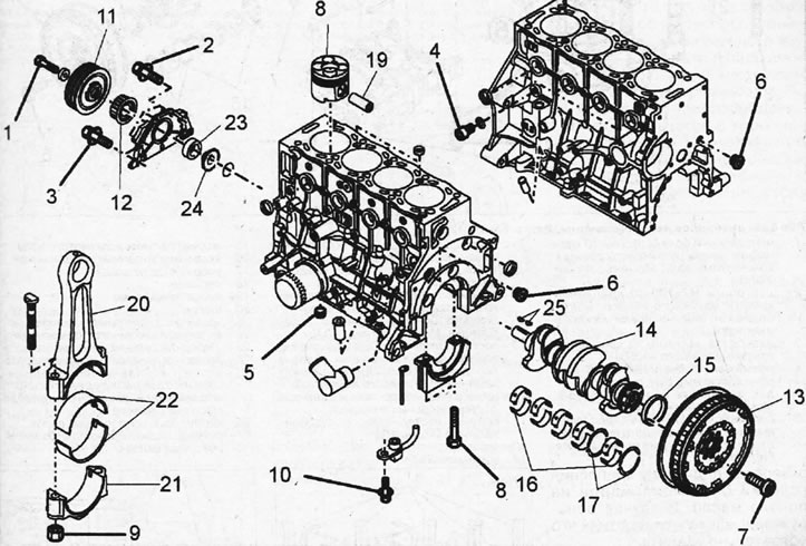
7.0. Cylinder block and its components. DW10ATED4 engine 1- central bolt M 14x150-70 for fastening the V-belt pulley to the crankshaft. Tightening torque 50 Nm; 2 - two M7x100-20 bolts for fastening the oil pump cover; 3 - two M7x100-40 bolts for fastening the oil pump cover. Bolts must be replaced after each dismantling; 4 - threaded plug M12x150-16. Tightening torque 25 Nm; 5-threaded plug M 15x150. Tightening torque 25 Nm; 6 - two threaded plugs M15x150-16. Tightening torque 40 Nm; 7 - eight M9x100-24 flywheel mounting bolts. Tightening torque 48 Nm. Bolt threads should be lubricated with Loctite Frenetancti sealant; 8 - bolts M12x150-81 for fastening main bearing caps. Tightening torque 25 Nm. Bolts must be replaced after each dismantling; 9 - eight M9x100 nuts for fastening the connecting rod bearing caps. Tightening torque 20 Nm; 10 - bolt M6x100-16 for fastening the oil intake. Tightening torque 10 Nm; 11 - pulley of the auxiliary drive V-belt; 12 - leading gear of the gas distribution mechanism; 13 - flywheel; 14 - crankshaft; 15 - rear crankshaft oil seal; 16 - main bearing shells; 17 - thrust half rings; 18 - piston; 19 - piston pin; 20 - connecting rod; 21 - connecting rod bearing cap; 22 - connecting rod bearing shells; 23 - front crankshaft oil seal; 24 - oil pump drive sprocket; 25 - keys for fastening the drive gear of the timing mechanism and the oil pump drive sprocket
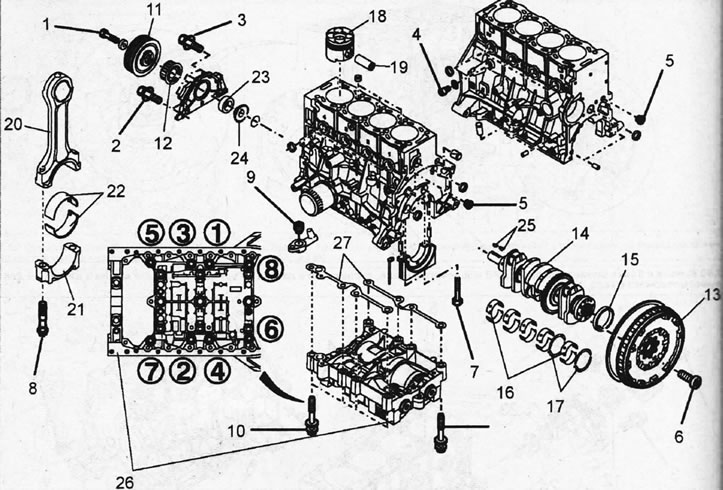
7.0a. Cylinder block and its components. DW12TED4 engine 1 - central bolt M14x150-70 for fastening the V-belt pulley to the crankshaft. Tightening torque 700 Nm; 2 - two M7x100-40 bolts for fastening the oil pump cover. Bolts must be replaced after each dismantling; 3 - two M7x100-20 bolts for fastening the oil pump cover; 4 - threaded plug M12x150-16. Tightening torque 25 Nm; 5 - two threaded plugs M15x150. Tightening torque 40 Nm; 6 - eight M9x100-24 flywheel mounting bolts. The bolt threads should be lubricated with Loctite Frenetanch sealant; 7 - ten M12x150-81 bolts for fastening the main bearing caps. Bolts must be replaced after each dismantling; 8 - eight M9x100-45 bolts for fastening the connecting rod bearing caps; 9 - bolt M6x100-16 for fastening the oil intake. Tightening torque 10 Nm; 10 - eight M8x125-60 bolts for fastening the balancing shaft housing and the order of their tightening. Bolts must be replaced after each dismantling; 11 - pulley of the auxiliary drive V-belt; 12 - leading gear of the gas distribution mechanism; 13 - flywheel; 14 - crankshaft
Inspect all parts carefully. If their surfaces show signs of corrosion, scratches, or their wear has reached acceptable limits, then such parts must be replaced.
When completely disassembling, thoroughly clean the cylinder block and remove all foreign particles from the cavities and lubrication channels.
The liquid used to flush and clean the unit must be completely removed. If possible, dry the unit with compressed air after cleaning. Make sure that in
no oil got into the holes for the cylinder head mounting bolts. If oil is found in the holes, be sure to remove it.
59. Fasten oil nozzles 4 to the cylinder block, tightening them with a force of 10±1 Nm, and also place liners 1 of the main bearings with grooves for oil supply and thrust half rings 2 and 3, the grooves in which should be facing the crankshaft (see illustration).
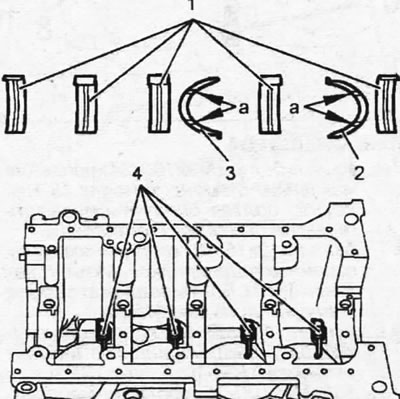
7.59. Fasten oil nozzles 4 to the cylinder block, and also place liners 1 of the main bearings and thrust half rings 2 and 3
Important! Measure the main bearing diameter to ensure you install bearing shells of the correct thickness.
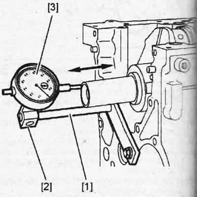
60. Install the crankshaft and check its axial runout by securing support 1 and 2 with a pointer indicator 3 to the cylinder block and pushing the shaft from the opposite side (see illustration). The axial runout of the crankshaft should be within 0.07 - 0.32 mm.
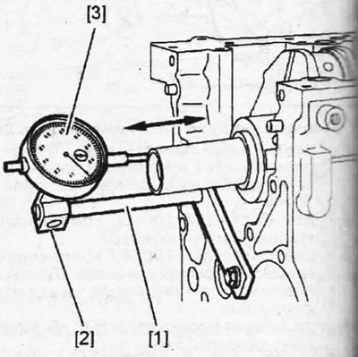
7.60. Install the crankshaft and check its axial runout by securing support 1 and 2 with a pointer indicator 3 to the cylinder block and pushing the shaft from the opposite side.
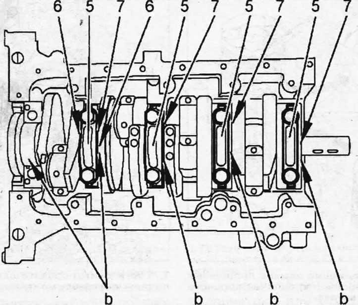
61. Lubricate the bearing journals "b" of the crankshaft and the shells 7 of the main bearings with clean engine oil, then lay the shells 2, 3, 4 and 5 of the bearings, install the thrust half rings 6 and the caps 5 of the bearings in the seats of the second main bearing, tightening their bolts by hand (see illustration).
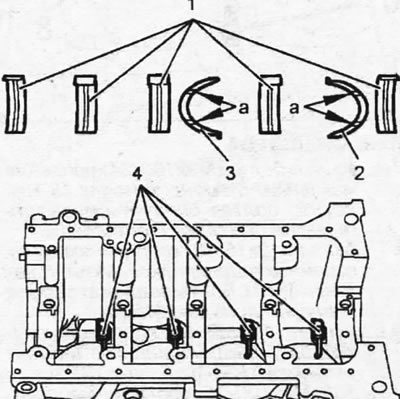
7.61. Lubricate the bearing journals "b" of the crankshaft and the shells 7 of the main bearings with clean engine oil, then lay the shells 2, 3, 4 and 5 of the bearings, install the thrust half rings 6 and the bearing caps in the seats of the second main bearing
Important! To install the first main bearing cap, a special tool is required to ensure proper installation of the cap side seals.
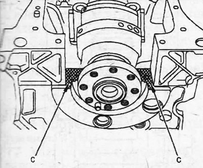
62. Apply E4 sealant to the "c" surfaces of the first main bearing housing (see illustration).
7.62. Apply E4 sealant to the "c" surfaces of the first main bearing housing
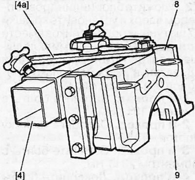
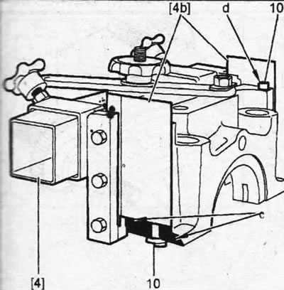
63. Fasten cover 8 of the first main bearing on device 4, pressing the cover with bar 4b, and insert liner 9 into the cover (see illustration).
7.63. Fasten cover 8 of the first main bearing on device 4, pressing the cover with bar 4b, and insert liner 9 into the cover
64. Insert two rubber seals 10 into the grooves on the cover secured in device 4, achieving a minimum protrusion "d" and lubricate the guide surfaces "e" with engine oil (see illustration).
7.64. Insert seals 10 into the grooves on the cover secured in device 4, achieving a minimum protrusion "d" and lubricate surfaces "e" with engine oil
65. Install the device 4 together with the main bearing cap 8 on the mounting place, moving it at a slight angle, screw in the cap bolts and remove the device 4 (see illustration).
7.65. Install fixture 4 together with main bearing cap 8 on the mounting location and centering bushings, secure with bolts and remove fixture 4
Attention! New seals 10, if they are correctly selected and installed, do not need to be cut.
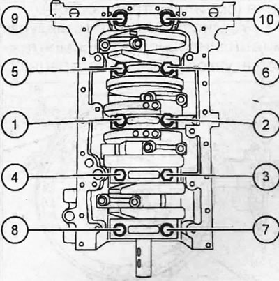
66. Tighten the main bearing caps in two passes, acting in ascending order of their numbering (see illustration).
7.66. Tighten the main bearing caps in two passes, acting in ascending order of their numbering
- 1st pass. Tighten the bolts to 25±2 Nm.
- 2nd pass. Tighten the bolts by 60±5°.
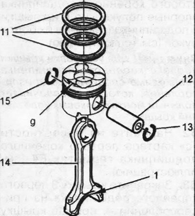
67. Install compression and oil scraper rings on the pistons 11 (see illustration).
7.67. Install compression and oil scraper rings on the pistons 11
Attention! The "TOP" inscription on the ring must face the piston bottom.
68. Assemble the piston and connecting rod 14, connecting them with the piston pin 12, which is secured with retaining rings 13 and 15 (see illustration 7.67).
Caution! Make sure the piston and connecting rod are correctly oriented relative to each other. The arrow "g" on the piston crown should point towards the timing drive, and the oil outlet hole "f" on the connecting rod should point towards the oil filter (see illustration 7.67).
69. Make sure that the locks "h", "j" and "k" of the piston rings are located at an angle of 120° relative to each other and fix the piston in the mounting sleeve 7, positioning the piston in it so that the lower part A of the piston skirt protrudes (see illustration).
7.69. Location of piston ring locks on the piston and fastening of the piston in the mounting sleeve
70. Lubricate the cylinder walls and liners of the 16 connecting rod bearings with engine oil and place the liners on the crankshaft journals (see illustration 7.69).
71. Install the pistons with connecting rods into the cylinders using the mounting sleeve 7 (see illustration).
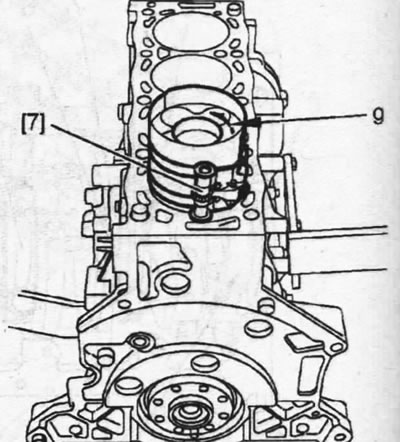
7.71. Install the pistons with connecting rods into the cylinders using mounting sleeve 7
Caution: Make sure the "g" arrow on the piston crown points towards the timing belt (see illustration 7.71).
72. Place the cylinder block with the crankcase facing up and install the connecting rod bearing caps 17 together with the second halves of the liners and secure with new bolts 18, tightening them in several passes (see illustration).
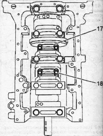
7.72. Install the caps 17 of the connecting rod bearings together with the second halves of the liners and secure with new bolts 18
- 1st pass. Tighten the bolts to 10±1 Nm.
- 2nd pass. Loosen the bolts by 180°.
- Pass 3: Tighten the bolts to 23±1 Nm.
- 4th pass. Tighten the bolts by 45±5°.
Please note: On vehicles with the DW10ATED4 engine, the connecting rod bearing caps are secured with nuts.
73. Fit the rear crankshaft oil seal.
74. Install flywheel 19 and secure it with two studs 8 (see illustration).
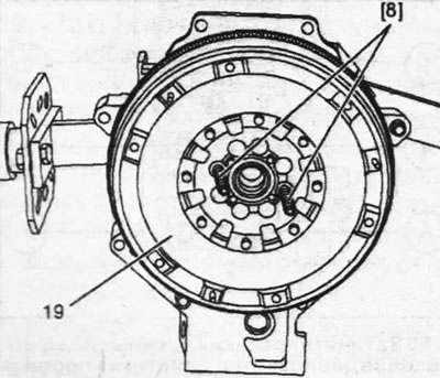
7.74. Install flywheel 19 and secure it with two studs 8
Attention! Workshops use cone studs to center the flywheel on the crankshaft (see illustration 7.75).
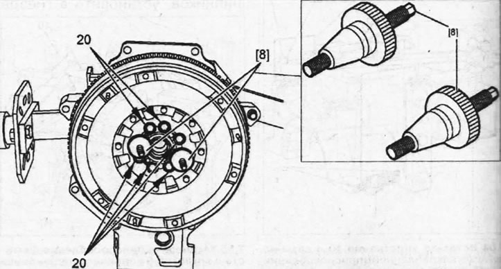
7.75. Center the flywheel on the crankshaft by screwing the cone-shaped bushings onto the installed studs 8 and screw in six bolts 20
75. Center the flywheel on the crankshaft by screwing the cone-shaped bushings onto the installed studs 8 and screw in the six bolts 20 with which the flywheel is secured (see illustration). After this, unscrew both studs 8 together with the cones and screw in the two remaining flywheel mounting bolts.
76. Lock the flywheel with a thrust shoe and tighten its mounting bolts in two passes, acting in a crisscross pattern.
- 1st pass. Tighten the bolts to 15 Nm.
- Pass 2: Tighten the bolts to 48 Nm.
77. Install sprocket 24 on the crankshaft at the same time, and oil pump 21 with chain 25 on the cylinder block, putting it on sprocket 24 (see illustration). After this, screw in the oil pump mounting bolts 22, following the markings made during dismantling, and tighten the bolts in two passes.
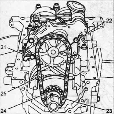
7.77. Install sprocket 24 on the crankshaft at the same time, and oil pump 21 with chain 25 on the cylinder block
- 1st pass. Tighten the bolts to 7 Nm.
- 2nd pass. Tighten the bolts to 10 Nm.
78. Move sprocket 24 on the crankshaft to the cylinder block, insert key 23 into the groove and fix the sprocket on it (see illustration 7.77).
79. Install the oil pump cover 26, applying E4 sealant to the surface mating with the cylinder block, screw in the bolts 27 and tighten them with a force of 15 Nm (see illustration).
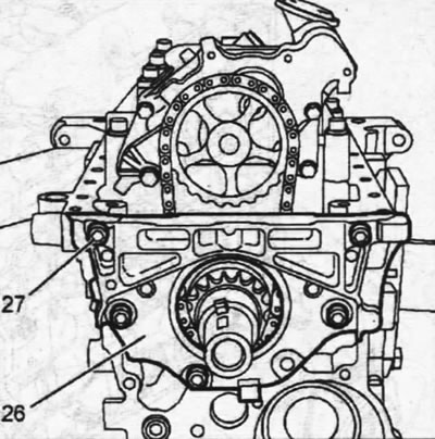
7.79. Install the oil pump cover 26, screw in the bolts 27 and tighten them to 15 Nm
80. Using a suitable mandrel 17a, drive in the front crankshaft oil seal (see illustration).
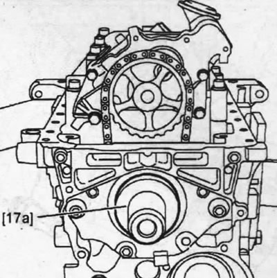
7.80. Using a suitable mandrel 17a, drive in the front crankshaft oil seal
Caution! To avoid damaging or twisting the seal, it is recommended to use an auxiliary sleeve to guide the seal onto the mandrel.
81. Install the oil pickup, the guide tube of the engine oil level dipstick and the oil pan (see illustration 7.0b).
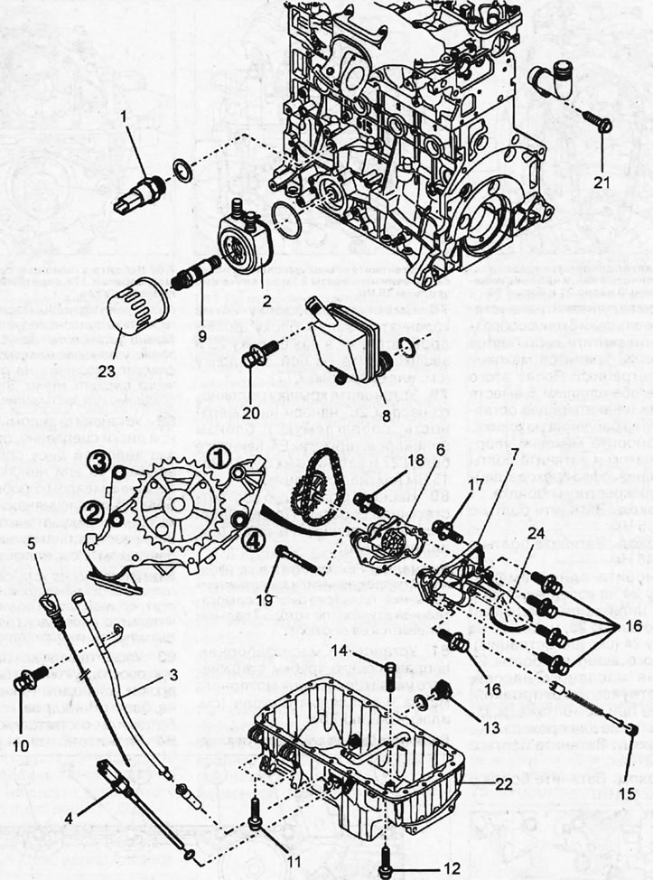
7.0v. Oil pump and engine lubrication system components 1 - engine oil pressure sensor; 2 - engine oil cooling radiator with sealing gasket; 3 - guide tube of the engine oil level indicator rod (dipstick); 4 - engine oil level sensor with sealing ring; 5 - engine oil level indicator rod (dipstick); 6 - oil pump housing with driving and driven gears; 7 - oil pump housing cover; 8 - oil separator; 9 - oil filter mounting pipe to the cooling radiator. Tightening torque 50 Nm; 10 - bolt M6x100-12 for fastening the guide tube. Tightening torque 10 Nm; 11 - two M7x100-40 bolts for fastening the oil pan. Tightening torque 16 Nm; 12 - twenty bolts M7x100-21 for fastening the oil pan. Tightening torque 16 Nm; 13 - drain plug on the oil pan. Tightening torque 35 Nm; 14 - bolt M6x100-12 for fastening the oil intake. Tightening torque 10 Nm; 15 - oil pump pressure relief valve plug. Tightening torque 20 Nm; 16 - five M6x100-30 bolts securing the oil pump cover to the housing; 17 - M6x100-30 bolt. To be replaced after dismantling; 18 - two M6x100-55 bolts. To be replaced after dismantling; 19 - bolt M6x100-52-24. To be replaced after dismantling; 20 - bolt M6x100-20 for fastening the oil separator. Tightening torque 10 Nm; 21 - branch pipe mounting bolt. Tightening torque 10 Nm; 22 - oil pan. When installing, the tray is sealed with E10 sealant; 23 - oil filter; 24 - oil intake with sieve
Important! The oil pan is sealed with E10 sealant. After applying the sealant, install the oil pan immediately. The engine should not be started earlier than thirty minutes after installing the oil pan. This time is necessary for the sealant to harden.
82. Install the driven and pressure plates of the clutch, centering the driven plate with a special roller 18 or the unused primary shaft of the gearbox. Tighten bolts 31 securing pressure plate 32 to the flywheel with a force of 20 Nm, locking the flywheel with thrust shoe 9 (see illustration).
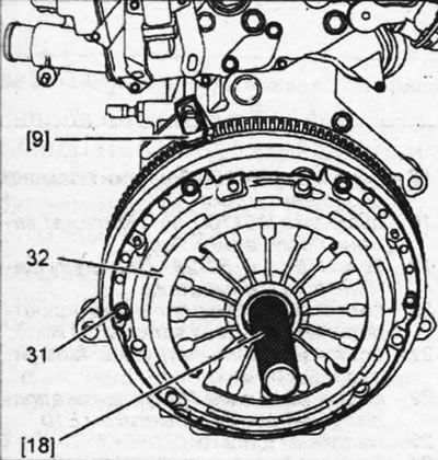
7.82. Install the driven and pressure plates of the clutch, centering the driven plate with a special roller 18
Attention! Before installing the cylinder head on the block, measure the piston protrusion to select the head gasket of the required thickness, see the relevant chapter.
83. Place a new cylinder head gasket and install the head assembly on the cylinder block and secure with bolts, see the relevant chapter.
84. Place the cylinder head cover 53 on it, screw in the thirteen mounting bolts 52 and tighten them in ascending numbering order with a torque of 10 Nm (see illustration).
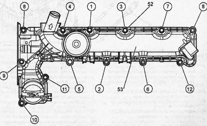
7.84. Place the cylinder head cover 53 on it, screw in the thirteen mounting bolts 52 and tighten them in ascending numbering order with a torque of 10 Nm
Note: The position of the exhaust camshaft is monitored by an inductive sensor, which must be located at a certain distance from the gear on the camshaft.
85. Install camshaft position sensor 55, secure it with bolt 54 and adjust the gap between the end of the sensor and its gear (see illustration). To adjust the gap, slide the sensor back until it rests against the mounting bolt and achieve a gap of 1.2 mm. Tighten the sensor mounting bolt to 20 Nm.
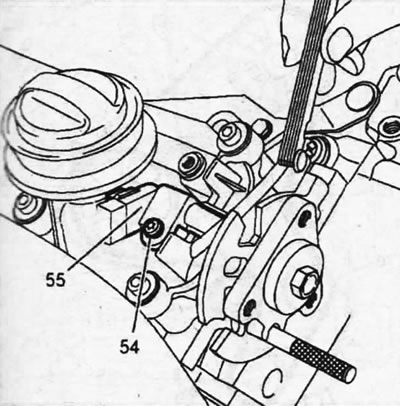
7.85. Install camshaft position sensor 55, secure it with bolt 54 and adjust the gap between the end of the sensor and its gear
86. Make sure that the centering pins on the support bracket 57 of the high-pressure pump are in their mounting locations and install the bracket on the cylinder head, securing it with bolts 56 with a torque of 20 Nm (see illustration).
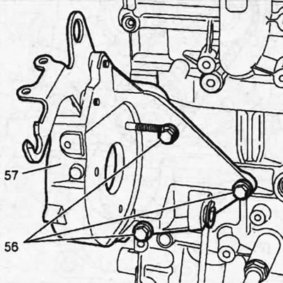
7.86. Install the fuel injection pump support bracket 57 and secure it with bolts 56
87. Install the high-pressure fuel pump 58 on the support bracket, screw in three bolts 60 and one bolt 59 and tighten them. The tightening torque of the bolts is 60 - 20 Nm, and the bolt 59 - 22 Nm (see illustration).
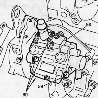
7.87. Install the high-pressure fuel pump 58 on the support bracket, screw in three bolts 60 and one bolt 59 and tighten them
88. Install the timing drive components (see illustration):
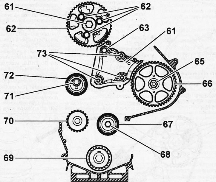
7.88. Install the timing drive components
- gear 74 of the camshaft, securing it to the hub with bolts 62 and central bolt 61. Tightening torque of bolt 61 - 45 Nm;
- crankshaft gear 69;
- gear 66 of the high-pressure fuel pump, securing it with nut 65 with a tightening torque of 55 Nm;
- guide roller 67, screwing in bolt 68 with a tightening torque of 45 Nm;
- water pump 70, installing a new sealing gasket,
- bracket 64 of the engine mount, securing it with bolts 73 and 63, the tightening torques of which are 50 and 22 Nm, respectively;
- tension roller 72, screwing in bolt 71.
89. Lock the crankshaft with stop 14 and the camshaft gear with stop 20 (see illustration).
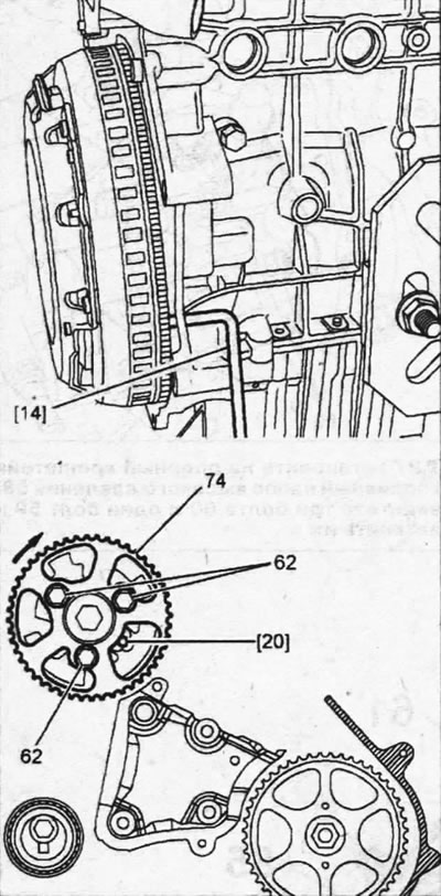
7.89. Lock the crankshaft with stop 14
90. Turn gear 74 on the camshaft hub clockwise so that the hub rests against bolts 62 (see illustration 7.89).
Caution! Bolts 62 should not be tightened to final torque. They should be tightened enough so that the gear can be moved on the hub if necessary. Typically, the tightening torque of the bolts during the belt tension adjustment stage is 20 Nm.
91. Place the toothed belt 75 on the crankshaft gear 69 and secure it with a special clamp 23 (see illustration).
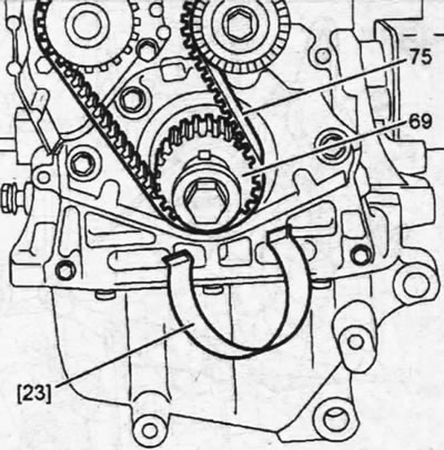
7.91. Place toothed belt 75 on crankshaft gear 69 and secure it with special clamp 23
92. Place the toothed belt on the guide roller 67, the gear 66 of the fuel injection pump, the gear 74 of the camshaft, the gear 70 of the water pump and the tension roller 73 (see illustration).
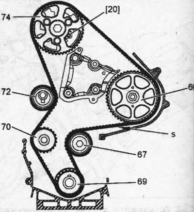
7.92. Timing belt installation procedure
Caution! If necessary, turn gear 74 on the hub counterclockwise, but not more than one belt tooth.
93. Remove stop 20, which was used to lock the camshaft gear, and tighten the toothed belt, installing the sensor of the measuring instrument 24 on the segment "t" between the gears of the fuel injection pump and the camshaft (see illustration).
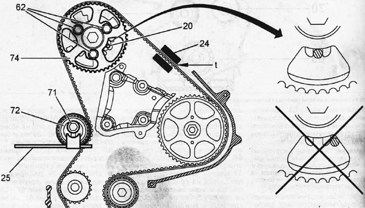
7.93. Tension the toothed belt by setting the sensor of the measuring instrument 24 to the "t" segment between the gears of the fuel injection pump and the camshaft
94. Turn tension roller 72 counterclockwise with key 25 so that the measuring device registers the tension of toothed belt 10672 SEEM and tighten bolt 71 of tension roller with a torque of 25 Nm (see illustration 7.93).
95. Make sure that the bolts 62 securing the camshaft gear to the hub do not rest against the ends of the elongated holes on the hub, but are located in the center of the holes. If necessary, you can unscrew one of the bolts for this purpose (see inset in Illustration 7.93).
Otherwise, the timing belt installation must be repeated.
96. Remove the timing belt tension measuring device and also remove stops 20 and 14, which were used to lock the camshaft and crankshaft and turn the crankshaft in the direction of engine travel by eight revolutions and again lock the crankshaft and camshaft and slightly loosen the tightening of bolts 62 of the camshaft gear (see illustration 7.93).
97. Install the sensor of the measuring device 24 on the belt, loosen the tightening of the bolt 71 of the tension roller 72 and turn its eccentric with the key 25 counterclockwise so that the measuring device shows the belt tension with a force of 5173 SEEM (see illustration 7.93).
98. Maintaining this belt tension, tighten the tension roller mounting bolt to 25 Nm and the camshaft gear bolts to 22 Nm.
99. Remove the measuring instrument and then reinstall it. The device should show the timing belt tension within 51±3SEEM.
Caution! If the instrument reading is different, the timing belt installation must be repeated.
100. Remove the stops, remove the measuring instrument, turn the crankshaft two revolutions and again lock the crankshaft and camshaft with the appropriate stops. If the timing belt is positioned correctly, the stops should fit into the holes without any problems. Deviation in the alignment of the holes of the camshaft gear and the cylinder head is allowed. This deviation should not exceed 1 mm. If the thrust rollers do not fit into the holes, the timing belt should be re-installed.
Please note: The timing belt routing on later production vehicles is slightly different from that shown above.
Timing belt installation on later model vehicles.
101. Lock the crankshaft with a suitable stop.
102. Secure the timing gear drive gear to the crankshaft using stop 16, inserting it to the left of the key. which holds the gear on the shaft (see illustration).
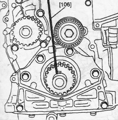
7.102. Fix the drive gear of the timing mechanism on the crankshaft with stop 16, inserting it to the left of the key
103. Lock gear 74 on the camshaft with stop 20, place the toothed belt on the gear and secure it on the gear with clamp 15 (see illustration).
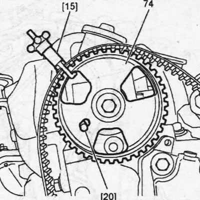
7.103. Lock gear 74 on the camshaft with stop 20, place the toothed belt on the gear and secure it on the gear with clamp 15
104. Install the timing belt, ensuring proper tension on the "t" section between the camshaft gears and the fuel injection pump, in the following sequence:
- gear 66 of the high-pressure fuel pump;
- guide roller 67;
- pinion gear 69;
- water pump gear 70;
- tension roller 72 (see illustration 7.105).
105. Attach the sensor of the 24 device for measuring the toothed belt tension to the "t" section between the camshaft gears and the fuel injection pump and tighten the belt (see illustration).
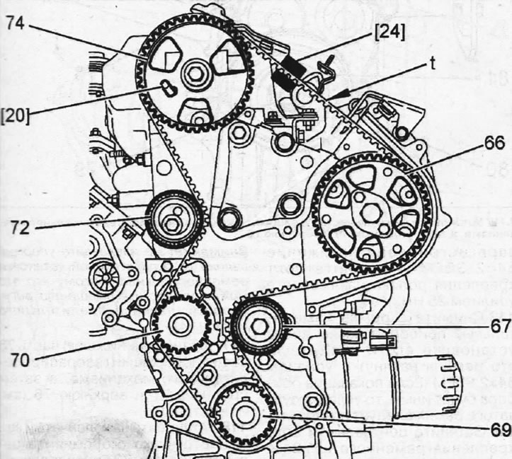
7.105. Attach the sensor of the device 24 for measuring the tension of the toothed belt to the section "t" between the gears of the camshaft and the fuel injection pump and tighten the belt
106. Remove clamp 15 from the camshaft gear and remove stop 16, which fixed the drive gear, and the stop, which locked the crankshaft.
107. Turn tension roller 72 with key 25 counterclockwise and tension the toothed belt with a force of 98±2 SEEM, which should be shown by the measuring device (see illustration).
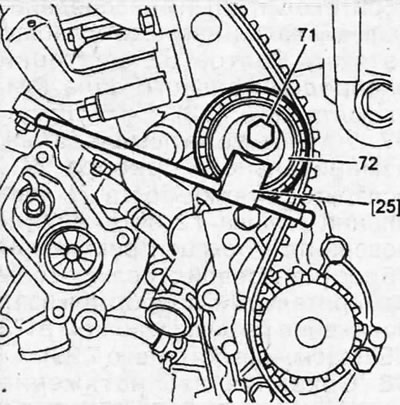
7.107. Turn tension roller 72 with key 25 counterclockwise and tension the toothed belt with a force of 98±2 SEEM
108. Holding the tension roller in this position, tighten bolt 71 of its fastening with a force of 25 Nm.
109. Lock the flywheel with a thrust shoe and install the V-belt pulley on the crankshaft, tightening the central bolt of its fastening with a force of 77 Nm.
110. Remove all stops and devices and turn the crankshaft eight revolutions in the direction of engine rotation.
111. Lock the crankshaft and camshaft gear, as well as the flywheel with a thrust shoe, loosen the tightening of the central bolt of the V-belt pulley, as well as the tension roller bolt and install a measuring device on the belt.
112. Turn the timing belt tension roller until the instrument registers a tension of 54±2 SEEM and tighten the tension roller mounting bolt to 25 Nm.
113. Remove the measuring device from the belt, then reinstall it and ensure that the belt is tensioned to 54±2 SEEM. If the device reading is different, the timing belt should be re-installed.
114. Tighten the central belt pulley mounting bolt to 77 Nm, remove the stops and turn the crankshaft two revolutions.
115. Lock the crankshaft and camshaft with the appropriate stops. If the timing belt is positioned correctly, the stops should fit into the holes without any problems. If the thrust rollers do not fit into the holes, the timing belt installation must be repeated.
116. Lock the flywheel with a thrust shoe and remove the V-belt pulley from the crankshaft by unscrewing the central bolt. This operation is necessary to install the protective cover of the timing mechanism.
Caution: Do not remove the thrust rollers until the belt pulley is fully installed, as this may cause the timing adjustment to shift.
117. Install the lower part 78 of the protective cover of the timing mechanism, and then the middle 77 and the upper 76 (see illustration).
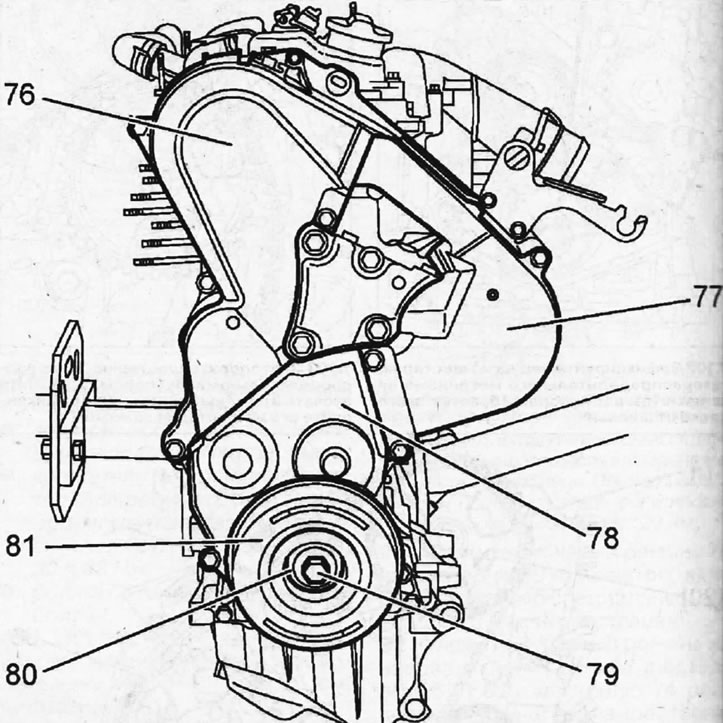
7.117. Install the lower part 78 of the protective cover of the timing mechanism, and then the middle 77 and the upper 76
118. Install the V-belt pulley 81 on the crankshaft and secure it with bolt 79 and washer 80 (see illustration).
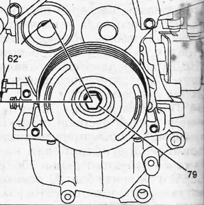
7.118. Install pulley 81 of the V-belt on the crankshaft and secure it with bolt 79 and washer 80
119. Lock the flywheel with a thrust shoe and tighten bolt 79 in two passes (see illustration 7.118).
- 1st pass. Tighten the bolt to 55 Nm.
- 2nd pass. Tighten the bolt 62±5°.
120. Install the fuel injectors with new sealing gaskets, the fuel rail and connect them with high-pressure fuel lines.
121. Install all remaining components in the reverse order of removal.