



Table of contents: Removal and disassembly 🠇 Installation 🠇
Removal and disassembly
1. Drain the coolant, see the relevant chapter.
2. Remove the windshield wiper mechanism, see the relevant chapter.
3. Remove the timing belt, see the relevant chapter.
4. Unscrew bolts 1 and 2, and then secure the right engine mount bracket, which was disconnected when removing the timing belt, to the cylinder block, tightening the bolts by hand (see illustration).
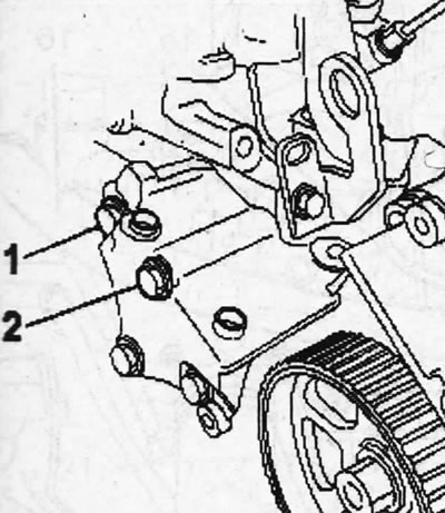
5.4. Unscrew bolts 1 and 2
5. Remove the support or garage jack from under the vehicle, which was used to lift the engine to relieve the load on the suspension mounts when removing the timing belt.
6. Place a container under the engine to collect condensate and fuel from the fuel filter that will flow out when the fuel lines are disconnected.
7. Unscrew fitting 3 and drain the condensate and fuel from the fuel filter (see illustration).
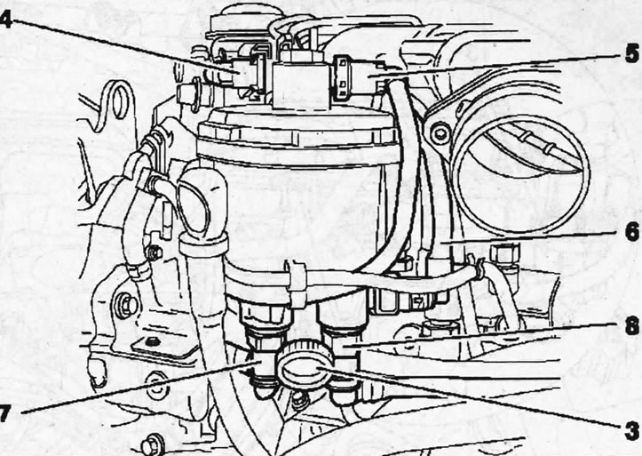
5.7. Unscrew fitting 3 and drain the condensate from the fuel filter
Disconnect fuel lines 4, 5, 6, 7 and 8 and seal their openings with suitable plugs (see illustration 5.7).
8. Disconnect the supply air duct 9 from the intake manifold 10 (see illustration).
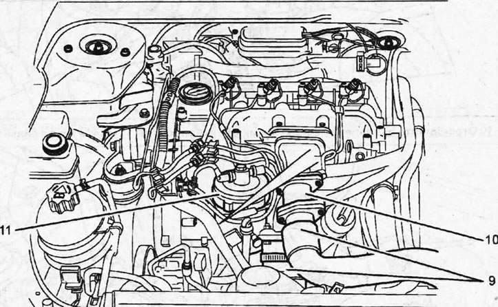
5.8. Disconnect the supply air duct 9 from the intake manifold 10
9. Remove the cover 11 from the fuel filter, and then remove the fuel filter bracket (see illustration 5.8).
10. Disconnect lines 12 and 14 from the EGR valve, remove clamp 13 and disconnect the low-pressure hoses (see illustration).
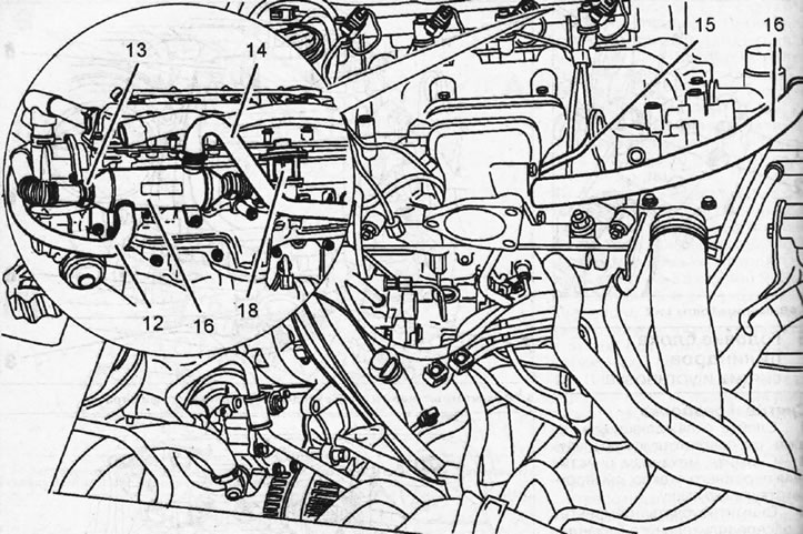
5.10. Disconnect pipes 12 and 14 from the EGR valve and remove clamp 13
11. Disconnect the exhaust gas recirculation line 16, and then remove the electromagnetic 18 and mechanical 17 valves of the recirculation system (see illustration 5.10).
12. Release the wire harness from the holders on the thermostat housing and move it to the side.
13. Disconnect bracket 19 (see illustration).
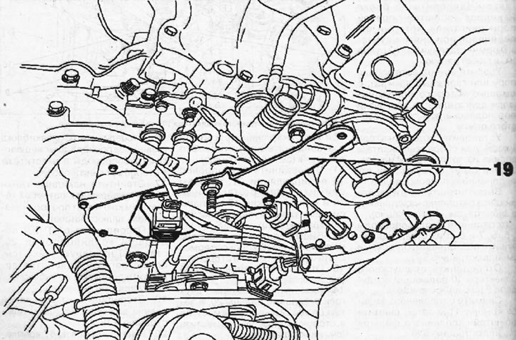
5.13. Disconnect bracket 19
14. Unscrew the threaded pins 20 using two nuts, then the bolts 22 and slightly move the thermostat housing 21 to the side (see illustration).
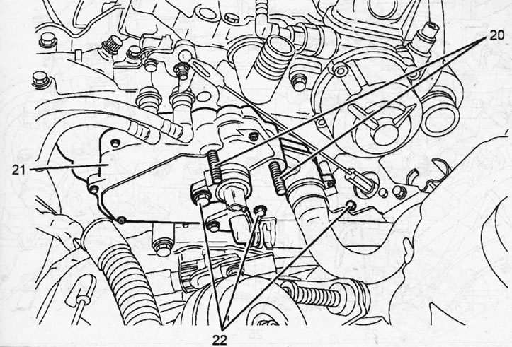
5.14. Using two nuts, unscrew the threaded pins 20, then the bolts 22 and slightly move the thermostat housing 21 to the side
15. Remove the camshafts, see the relevant chapter.
16. Disconnect the wires, hoses and pipes from the cylinder head and move them away from the work area.
17. Unscrew union nuts 23 and 24, holding pipe "a" with a wrench from turning (see illustration).
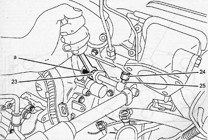
5.17. Unscrew union nuts 23 and 24, holding pipe "a" with a wrench from turning
18. Disconnect the fuel supply line 25 from the high-pressure fuel pump by unscrewing the union nut (see illustration). Seal the holes with plugs to prevent contamination from entering.
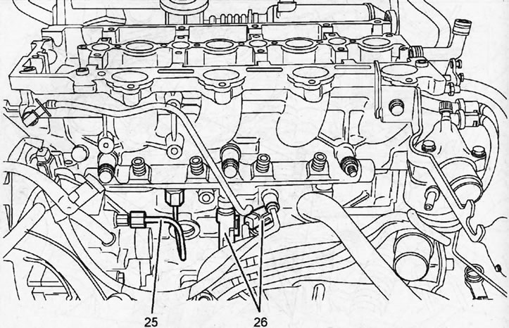
5.18. Disconnect the fuel supply line 25 from the high-pressure fuel pump by unscrewing the union nut
19. Disconnect the connectors 26 from the fuel rail (see illustration 5.18).
20. Unscrew the 67 cylinder head mounting bolts, loosening them in ascending numbering order (see illustration).
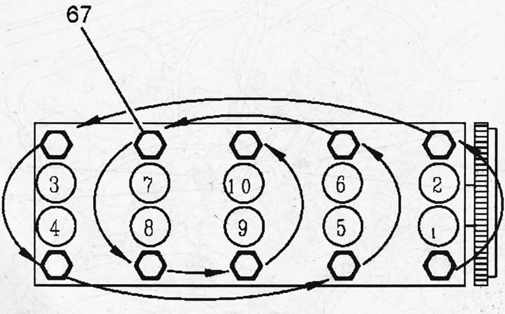
5.20. Unscrew the 67 cylinder head mounting bolts, loosening them in ascending numbering order
21. Loosen the seat of the head on the cylinder block and remove it, as well as its sealing gasket (see illustration). Usually the cylinder head is removed using special levers.
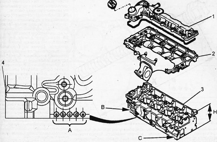
5.21. Cylinder head and its components 1 - cylinder head cover A; 2 - camshaft bearing housing Made of alloy B - light metals; 3 - cylinder head. Made of light metal alloy; 4 - cylinder head gasket; A - sealing gasket marking; B - in this place there is a mark indicating the possibility of drilling holes in the camshaft bearing housing. Drilling tolerance +0.5 mm.; C - in this place a mark is placed indicating the possibility of grinding the cylinder head. If grinding is allowed, then the head is marked with the letter B; H – cylinder head height.
Installation
22. Clean the mating surfaces of the cylinder head and block.
Caution: Use a plastic or wooden scraper to clean the aluminum alloy. Do not use tools with sharp edges to clean the cylinder head. Prevent dirt from entering the cylinder bores. Plug their holes with a clean rag. Clean the channels if necessary.
23. Check the cylinder head for deformation and warpage using a standard steel ruler (see illustration). Permissible cylinder head deformation should not exceed 0.05 mm. The cylinder head can be modified. Nominal head height is 133.0 ±0.05 mm. Permissible residual height after finishing is 132.6 ±0.05 mm.
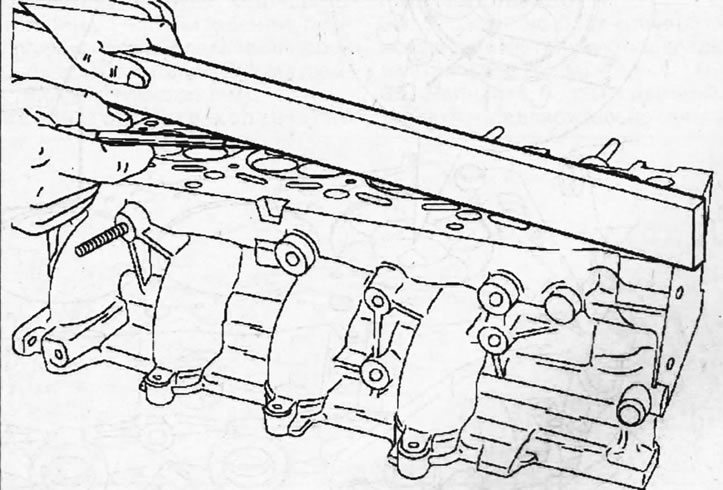
5.23. Check the cylinder head for deformation and warping using a standard steel ruler
24. Clean the threads in the cylinder block holes for the head mounting bolts using an M12x150 tap. These holes should be free of oil or other contaminants. If necessary, blow out the holes with compressed air or clean them with a screwdriver wrapped in a rag that will absorb the liquid. Oil can be collected from the holes using a grease gun. Failure to do so will create excess pressure in the holes when tightening the bolts, which could lead to a rupture of the cylinder block or improper tightening of the bolts.
25. Visually inspect the condition of the valves, their springs and support plates, camshafts and their bearings, rocker arms and hydraulic tappets.
26. Measure the length of the cylinder head mounting bolts. The length of their rods X, measured from the lower surface of the bolt head, must not exceed 134.0 mm (see illustration). Otherwise, the bolts should be replaced with new ones. The length of the new bolt rod is 131.5 mm.
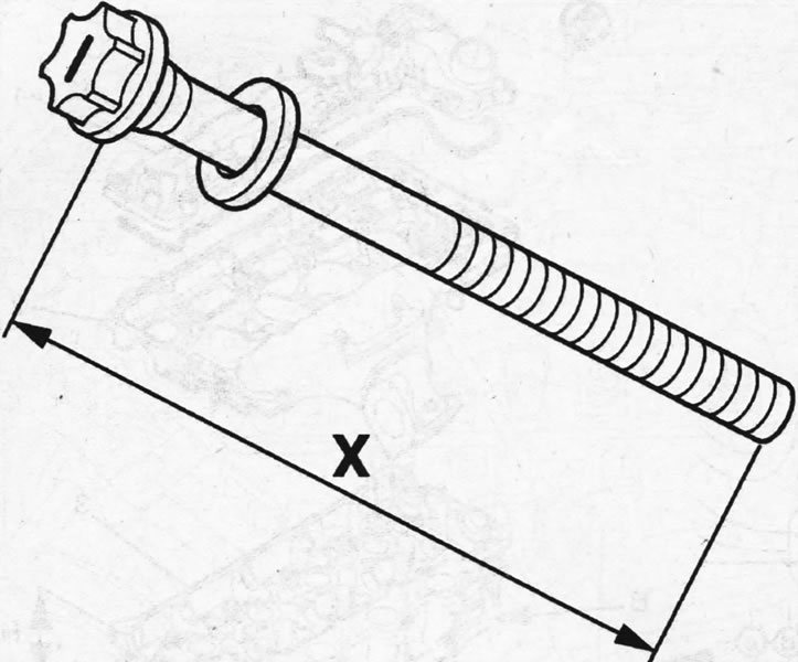
5.26. Measure the length X of the cylinder head bolts
Important! If the cylinder head was removed only to replace the sealing gasket and it was not ground, then during assembly, a new sealing gasket of the same thickness and with the same markings as the previous one must be installed. If the head has been modified, then, in addition to installing valves of a repair size, it is necessary to select a new sealing gasket of the required thickness. The selection of the gasket is performed after measuring the piston protrusion.
27. Measure the valve protrusion if the cylinder head has been modified, using an arrow-type indicator 4 on the support bracket 5 (see illustration).
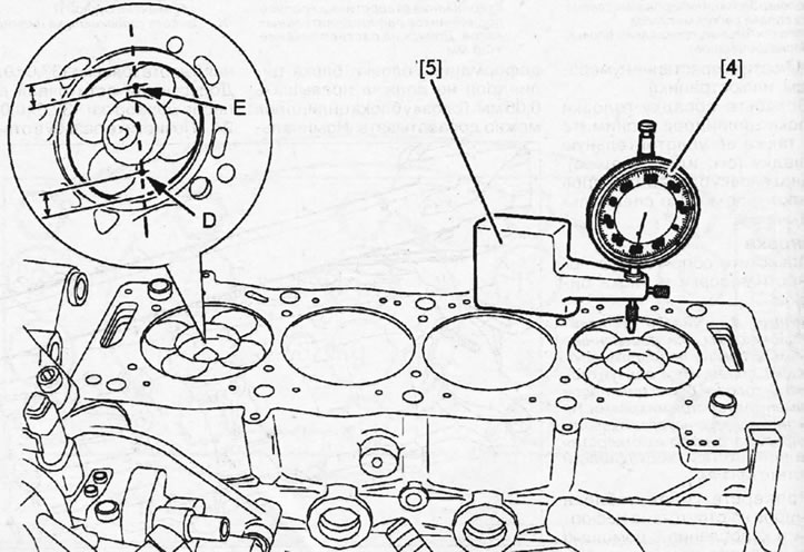
5.27. Measure the valve protrusion using an arrow-type indicator 4 on the support bracket 5
28. Place a zeroed dial indicator over the appropriate piston to measure the protrusion at point D and rotate the crankshaft by the center belt pulley mounting bolt until the piston reaches TDC. Once the piston reaches TDC and touches the dial indicator tappet, read the dial indicator reading and record it (see illustration 5.27).
Caution! Do not turn the crankshaft like this. so that the piston, the protrusion of which is being measured, exits TDC.
29. Turn the crankshaft back 1/4, remove the indicator, reset it to zero and reinstall it on the cylinder block surface to measure the piston protrusion at point E (see illustration 5.27).
30. Turn the crankshaft until the piston reaches TDC, read the dial indicator and also write it down. Measure the protrusion of the remaining pistons in the same sequence.
31. Add both readings for each piston and divide by two to get the average. The difference in the average piston protrusion values of two adjacent pistons should not exceed 0.07 mm. The maximum piston protrusion value determines the thickness of the sealing gasket that will need to be installed. The thickness of the cylinder head gasket is determined by the number of holes (see illustration).
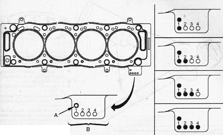
5.31. Marking of the sealing gasket A - engine designation; B - holes indicating the thickness of the gasket
| Piston protrusion Gasket thickness | Number of holes (A) | Number of holes (B) | |
| 0,55-0,60 | 1,25+0,04 | 1 | 1 |
| 0,61-0,65 | 1,30+0,04 | 1 | 2 |
| 0,66-0,70 | 1,35±0,04 | 1 | 3 |
| 0,71-0,75 | 1,40±0,04 | 1 | 4 |
32. Lock the crankshaft with a thrust roller. If necessary, turn the shaft until the holes on the cylinder block and the shaft cheek align.
33. Make sure that the centering pins 28 are in their places on the cylinder block (see illustration).
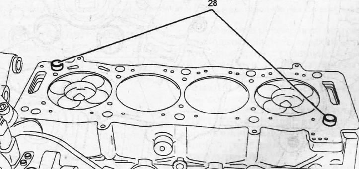
5.33. Make sure that the centering pins 28 are in their places on the cylinder block
34. Place a new sealing gasket on the cylinder block and install the head.
35. Screw in the head mounting bolts, having previously lubricated the threads and the bottom of the bolt heads with MOLYKOTE G RAPID PLUS (see illustration).
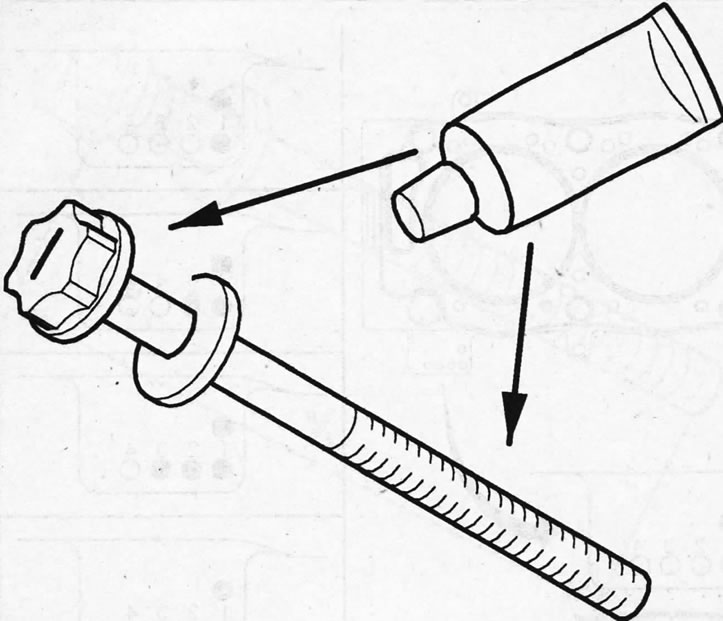
5.35. Lubricate the threads and the underside of the bolt heads with MOLYKOTE G RAPID PLUS
36. Tighten the cylinder head bolts in several passes, acting in ascending order of their numbers (see illustration):
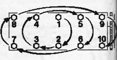
5.36. Tighten the cylinder head bolts in several passes, acting in ascending order of their numbers
- 1st pass - 20 Nm;
- 2nd pass - 60 Nm;
- 3rd pass - loosen the bolts one full turn;
- 4th pass - 20 Nm;
- 5th pass - tighten the bolts by 220°.
Subsequent tightening of the cylinder head bolts is not required.
37. Connect the high-pressure fuel supply line and the high-pressure fuel lines to the injectors and fuel rail.
38. Place the camshafts, see the relevant chapter.
39. Connect the thermostat housing 21, lubricating the threaded pins 20 with Loctite Freinfilet sealant (see illustration). Threaded pins 20 and bolts 22 for fastening the thermostat housing are tightened with a force of 25 Nm.
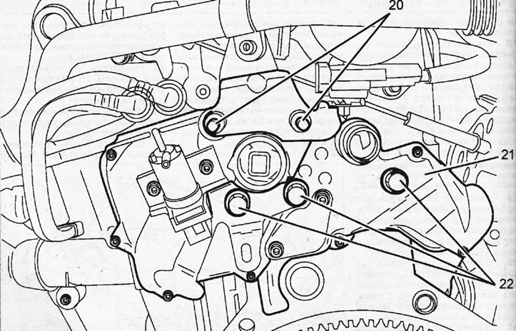
5.39. Connect the thermostat housing 21, lubricating the threaded pins 20 with Loctite Freinfilet sealant
40. Install the camshaft bearing housing, applying Loctite 518 sealant to the sealing surfaces of the cylinder head.
41. Install the cylinder head cover.
42. Place the timing belt, see the relevant chapter.
43. Connect all other pipes, hoses, wires and their plugs, as well as the parts removed to dismantle the cylinder head, acting in the reverse order of removal.