



Table of contents: Outer hinge 🠇 Inner hinge 🠇
Outer hinge
1. Remove the axle shaft as described in paragraph 2.
2. Release the outer clamp of the rubber boot by cutting it with a hacksaw (figure 4.2). Release the clamp and remove it from the cover.
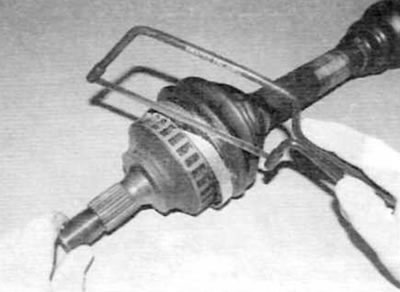
Figure 4.2. Release the outer clamp of the rubber boot by cutting it with a hacksaw
3. Using a screwdriver, loosen the inner clamp of the rubber boot, and then, using quick-drying paint, mark the position of the end of the boot on the axle shaft (figure 4.3, a.b).
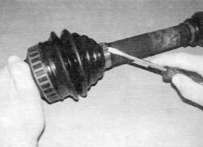
Figure 4.3, a. Using a screwdriver, loosen the inner clamp...
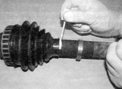
Figure 4.3, b....then mark the position of the end of the boot on the axle shaft
4. Slide the rubber boot off the axle shaft to expose the outer constant velocity joint and wipe off any excess grease (figure 4.4). It is recommended to wear rubber gloves when performing this operation.
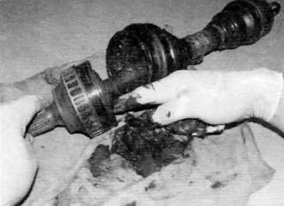
Figure 4.4. Remove the axle shaft boot and remove excess grease
5. Hold the axle shaft and use a hammer to sharply hit the end of the outer joint to knock it out of the end of the axle shaft (figure 4.5). The joint is supported on the axle shaft by a retaining ring, and releasing the joint in this manner releases the retaining ring, allowing the joint to be removed.
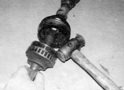
Figure 4.5. Sharply tap the edge of the outer joint to remove it from the end of the axle shaft
6. After removing the joint assembly, remove the retaining ring from the groove on the splined end of the axle shaft and discard it (figure 4.6). A new retaining ring must be installed during assembly.
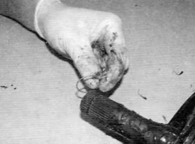
Figure 4.6. Remove the snap ring from the groove on the splined end of the axle shaft
7. Remove the rubber boot from the axle shaft and slide off the inner clamp.
8. After removing the constant velocity joint from the axle shaft, wipe off as much of the "old" grease as possible (do not use solvent) from the hinge so that its elements can be examined.
9. Move the internal spline drive from side to side to open each ball in turn at the top of its corresponding track. Inspect the balls for cracks, dents, or signs of surface pitting.
10. Inspect the ball tracks on the inner and outer elements. If the tracks are broken, the balls will not fit tightly. At the same time, check the separator for wear on the cells or cracks between the cells.
11. If any components of the constant velocity joint are worn or damaged, the entire joint assembly or even the entire axle shaft will need to be replaced (if no hinge components are supplied separately). For more information on spare parts, contact your Peugeot/Citroën dealer. If the joint is in satisfactory condition, purchase a repair kit. consisting of a new boot, snap ring, clamps and the correct amount of grease.
12. To install the new cover, follow the steps shown in the figures (Figure 4.12, a-o). Follow the prescribed sequence and strictly adhere to the captions under the figures. Please note that different types of clamps may be used, but the installation procedure will be similar to that shown.
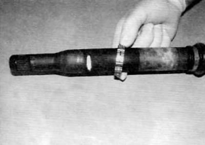
Figure 4.12, a. Place the new inner boot clamp onto the axle shaft...
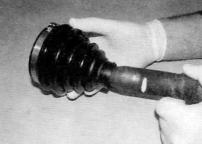
Figure 4.12, b....then a new cover with an external clamp
(Original is contained on the portal: «Peugeotbook.ru»)
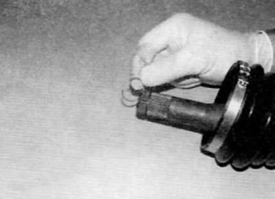
Figure 4.12, c. Install the new retaining ring into the groove on the axle shaft...
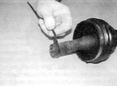
Figure 4.12, d....then tighten the retaining ring with a clamp
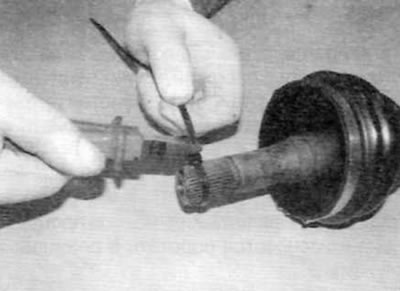
Figure 4.12, d. Using side cutters, tighten the clamp as tightly as possible, and then cut off the ends
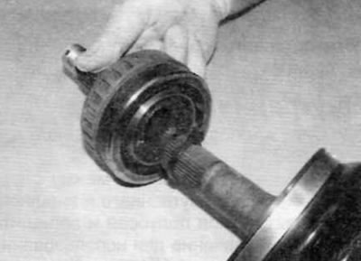
Figure 4.12, e. Slide the hinge onto the splined end and bring the inner element to the clamp
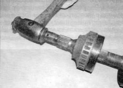
Figure 4.12, g. Give the end of the hinge a sharp blow to dislodge the clamp and slide the inner element over the retaining ring
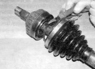
Figure 4.12, 3. After installing the hinge, cut off the clamp
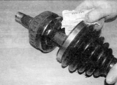
Figure 4.12, i. Pack the joint with the recommended lubricant; take half of the prescribed amount of lubricant...
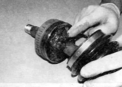
Figure 4.12, k....introduce grease into the ball races while rotating the hinge
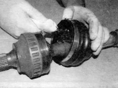
Figure 4.12, l. Fill the boot with the remaining grease...
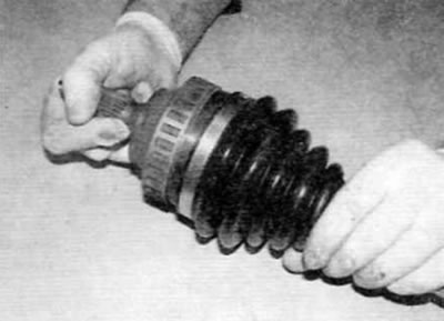
Figure 4.12, m....then slide the cover onto the outer element of the hinge and fix it in the corresponding groove
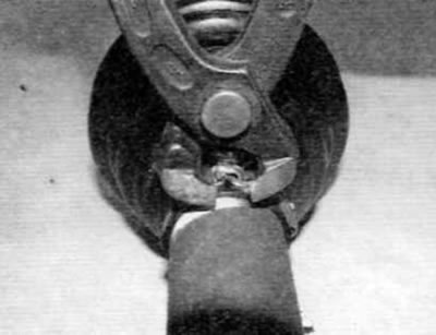
Figure 4.12, n. Insert the inner end of the boot into the groove on the axle shaft, using the mark made during removal as a guide, install the clamp and squeeze its protruding part using side cutters
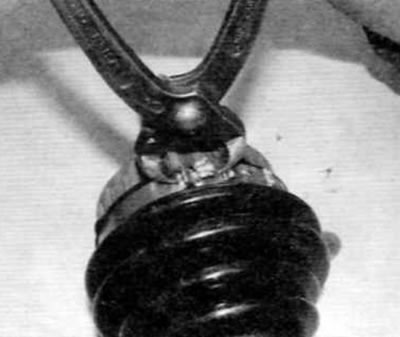
Figure 4.12, o. Similarly, secure the outer clamp of the cover
13. Make sure the constant velocity joint moves freely in all directions, then install the axle shaft on the vehicle as described in paragraph 2.
Inner hinge
14. Remove the axle shaft as described in paragraph 2.
15. Measure the distance between the inner edges of the inner and outer rubber axle shaft boots and record the measurement for use during installation (figure 4.15).
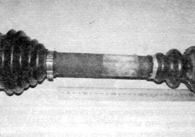
Figure 4.15. Measure and record the distance between the inner edges of the inner and outer axle shaft boots
16. Release the inner and outer clamps of the rubber boot by cutting them with a hacksaw (figure 4.16). Loosen the clamps and remove them from the cover.
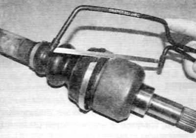
Figure 4.16. Release the cover clamps by cutting them with a hacksaw
17. Remove the outer hinge element from the tripod and remove the spring and thrust cap from the outer element (figure 4.17, a, b). After removing the outer element, check whether the rollers are secured to the tripod using caulking or retaining rings. If the rollers are not secured to the tripod, wrap the tripod with tape to hold them in place.
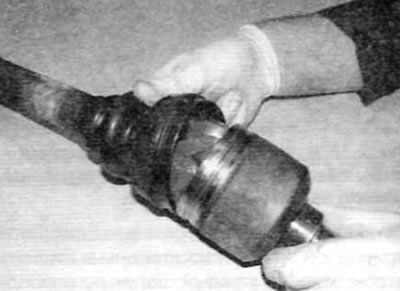
Figure 4.17, a. Remove the outer hinge element from the tripod...
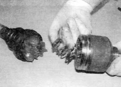
Figure 4.17, b....and remove the spring and thrust cap from the outer element
18. Remove as much excess grease as possible from the tripod and support rollers (figure 4.18). It is recommended to wear rubber gloves when performing this procedure.
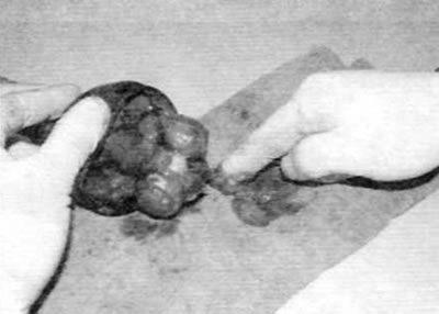
Figure 4.18. Remove as much grease as possible from the tripod and rollers
19. The tripod can now be removed using a two or three jaw hydraulic bearing puller or a press. When using a puller, secure its jaws behind the tripod so that they do not contact the hinge rollers. Using a press, support the underside of the tripod and press the axle shaft out of the joint (figure 4.19).
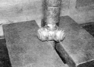
Figure 4.19. Remove the tripod using a hydraulic bearing puller with two or three jaws or a press
20. After removing the tripod, slide the boot off the end of the axle shaft.
2.1 Remove as much "old" grease as possible (do not use solvent) from the hinge so that its elements can be examined. Inspect the tripod. rollers and outer element for signs of damage or wear. Check the smooth movement of the rollers on the tripod pins. If there is wear or damage, the entire hinge assembly should be replaced (if possible) or even the entire axle shaft (if no hinge components are supplied separately). For more information on spare parts, contact your Peugeot/Citroën dealer. If the joint is in satisfactory condition, purchase a repair kit consisting of a new boot, clamps, and the correct amount of grease.
22.. To install the new cover, follow the steps shown in the figures (Figure 4.22, a-l). Follow the prescribed sequence and strictly adhere to the captions under the figures. Please note that different types of clamps may be used, but the installation procedure will be similar to that shown.
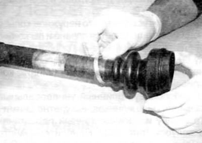
Figure 4.22, a. Place the new inner clamp and boot on the axle shaft
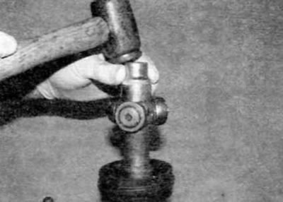
Figure 4.22, b. Clamp the axle shaft in a vice, place the tripod on the splines and lower it into its standard position
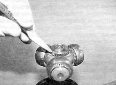
Figure 4.22, c. Using a small center punch, mark the tripod on the axle shaft in three places
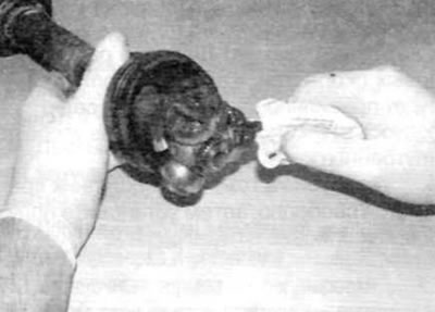
Figure 4.22, d. Fill the tripod and cover with grease; take half of the prescribed amount of lubricant...
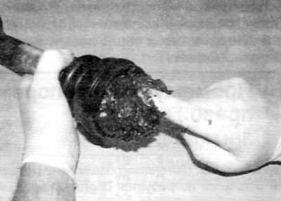
Figure 4.22, d....introduce grease into the bearing rollers
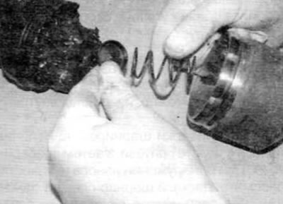
Figure 4.22, e. Install the spring and thrust cap into the outer element...
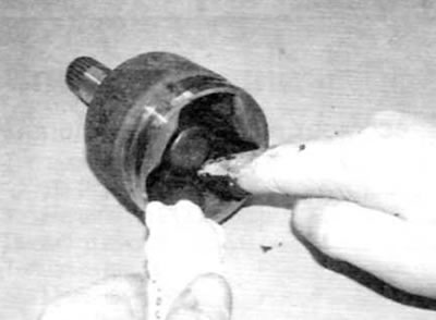
Figure 4.22, f....then fill the outer element with the remaining grease
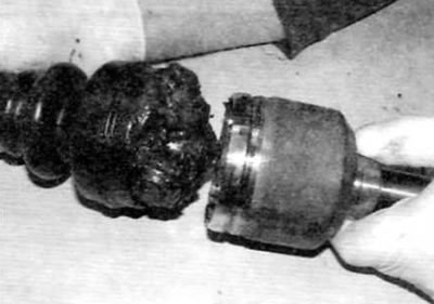
Figure 4.22, 3. Install the outer element on the tripod and fix the cover in the groove of the outer element
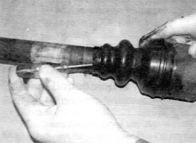
Figure 4.22, i. Place the outer element completely onto the tripod and lift the inner edge of the cover to release air from underneath it
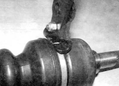
Figure 4.22, k. Install the outer clamp on the cover and squeeze its protruding part using side cutters
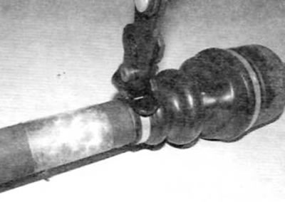
Figure 4.22, l. Position the inner end of the cover according to the size recorded during removal, slide the clamp on and crimp the protruding part
23. Make sure the constant velocity joint moves freely in all directions, then install the axle shaft on the vehicle as described in paragraph 2.