



- inertial puller 0316-A;
- shock absorber imitation device;
- key head 0539-C.
Remove the torsion bars in the following order:
- remove the shock absorber when the car is on its wheels;
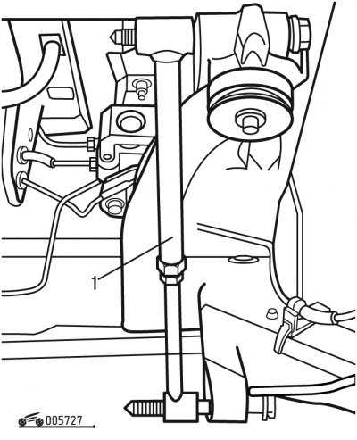
Figure 7.27. Installing a device simulating a shock absorber: 1 - device
- install device 1 instead of the shock absorber (figure 7.27), simulating a shock absorber, and secure it with nuts;
- raise the rear of the vehicle and place it on stands;
- remove the rear wheels;
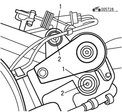
Figure 7.28. Unscrewing the torsion bar bolts: 1 - thrust washers; 2 - bolts
- unscrew bolts 2 (figure 7.28) and remove the thrust washers 1;
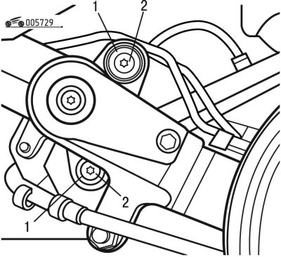
Figure 7.29. Unscrewing the torsion bar bolts: 1 - thrust washers; 2 - bolts
- unscrew bolts 2 (figure 7.29) and remove the thrust washers 1;
- mark the position of the lever relative to the torsion bar with two blows of a chisel;
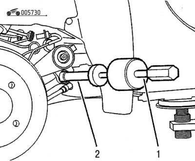
Figure 7.30. Installing the inertial puller: 1 - inertial puller; 2 - device
[Material copied from the resource peugeotbook.ru]
- install fixture 2 (figure 7.30) at the end of the torsion bar;
- install the inertial puller 1 on the device;
- press on the torsion bar to release it;
- to remove the torsion bar, pull it;
- hold the lever to prevent it from returning back to the torsion bar;
- remove tool 2 and inertial puller 1;
Caution: Before removing the shock absorber imitation device, lock the lever to hold it in its original position.
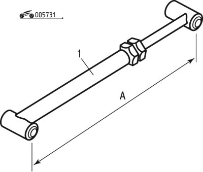
Figure 7.31. Device simulating a shock absorber: 1 - device; A - installation size
- remove the shock absorber imitation device and record dimension A (figure 7.31).
Install the torsion bars in the following order:
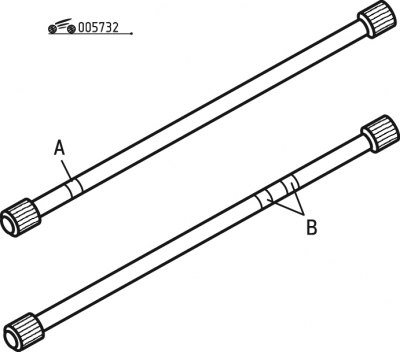
Figure 7.32. Markings on torsion bars: A - one mark; B - two marks
1) adjust size A (see figure 7.31) devices: by the amount determined for the correction of the reference height; by the amount specified in the characteristics when replacing the lever; by the amount obtained during dismantling;
Attention! Do not mix up the levers when installing. The right lever is connected to the torsion bar with a round mark A (figure 7.32) paint. The left arm is connected to a torsion bar that has two round marks B applied with paint.
2) clean the torsion bar splines and the inner splines of the levers;
3) lubricate the splines of the levers with ESSO NORVA 275 grease;
4) insert the torsion bar across the lever mount:
- in case of correction of the reference height, move the marks made during dismantling to the required number of splines;
- if you are installing a new torsion bar, turn the torsion bar one spline until you find a position where it fits freely by 8-10 mm;
- in other cases, align the marks made during dismantling;
Note: The torsion bar is not inserted to the full length of its splines: its ends are not located on the same axis, since the ends of the torsion bar have an even number of splines. There are two diametrically opposed positions in which the torsion bar is freely installed without changing the reference height.
5) Complete the installation to the stop using tool 2 (see figure 7.30) and inertial puller 1;
6) remove the device and puller;
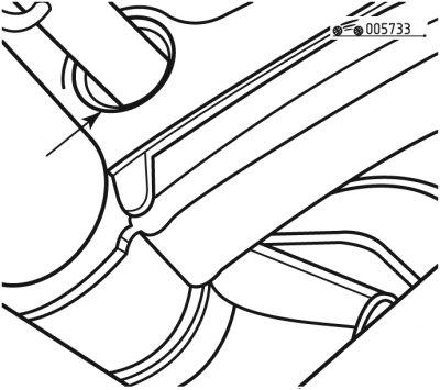
Figure 7.33. Filling the socket with grease
7) fill the nest (figure 7.33) eSSO NORVA 275 grease;
8) Apply grease to the ends of the torsion bar splines;
9) install thrust washers 1 (see figure 7.28) and tighten bolts 2 to 20 Nm;
10) install thrust washers 1 (see figure 7.29) and tighten bolts 2 to 20 Nm.