



Table of contents: Gearbox BE4 🠇 Gearbox MA 🠇
Gearbox BE4
Remove the clutch drive cable in the following order:
- remove the battery;
- remove the battery tray;
- remove the air filter with sleeves;
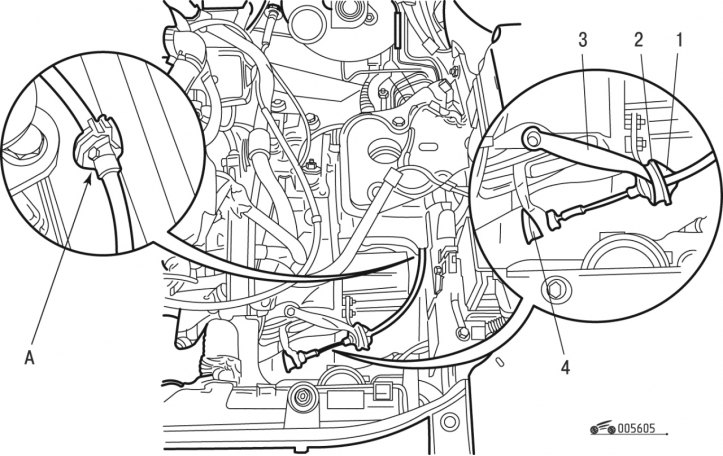
Figure 6.5. Clutch cable drive (gearbox BE4): 1 - cable sheath tip; 2 - bushing; 3 - support; 4 - bushing
- move tip 1 (figure 6.5.) cable sheath and bushing 2 supports 3 cables;
- remove bushing 4 from the clutch release fork lever;
- remove the cable from the retainer at location A;
- disconnect the cable from the clutch pedal;
- pull the cable at the level of the corrugated protective casing located under the brake booster;
- bend the cable around the gearbox housing and remove it.
Install the clutch drive cable in the following order:
- insert the cable into the hole in the front shield, having previously lubricated the plug with a soap solution to facilitate the cable routing;
- connect the end of the cable to the pedal;
- place the cable in the engine compartment in the same way as it was before removal;
- install bushing 4 on the clutch release fork lever;
- move away the sleeve 2 of the end 1 of the cable sheath;
- lubricate the flange of the bushing 2, the cylindrical end of the tip 1 of the cable sheath with consistent grease;
- insert bushing 2 into support 3 of the cable and then end 1 of the cable sheath into the bushing;
- install the coupling into the retainer at location A;
- install the remaining parts and components in the reverse order of removal;
- check the clutch operation.
Gearbox MA
Remove the clutch drive cable in the following order:
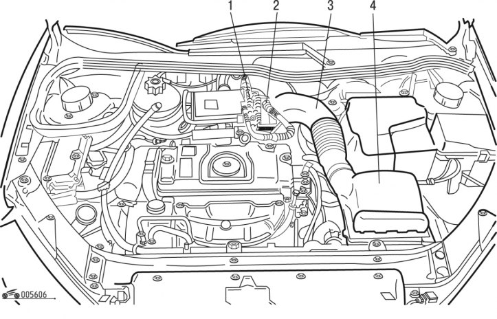
Figure 6.6. Air filter: 1 - clamp; 2 - crankcase ventilation tube; 3 - sleeve; 4 - air filter
- remove clamp 1 (figure 6.6) using a device;
- remove the crankcase ventilation tube 2;
- remove air filter 4 and sleeve 3;
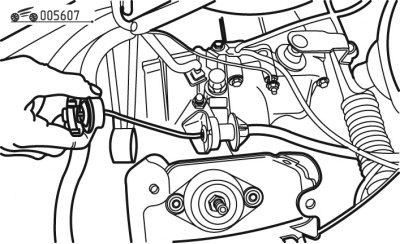
Figure 6.7. Pulling out the clutch cable
- pull the rope (figure 6.7) clutch actuator, then remove it from the clutch release fork lever;
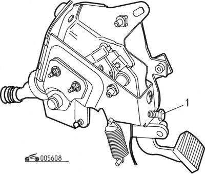
Figure 6.8. Limit bolt: 1 - bolt
- if this is not possible, i.e. the automatic gap compensation mechanism is blocked, unscrew bolt 1 (figure 6.8) to create a minimum gap on the clutch pedal;
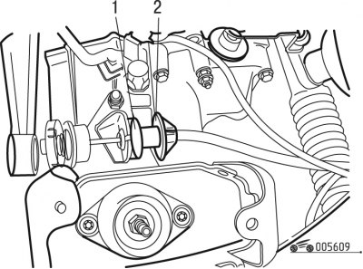
Figure 6.9. Cable fastening: 1 - coupling; 2 - casing tip
(Original can be viewed at: peugeotbook.ru)
- remove tip 2 of the casing (figure 6.9) and coupling 1;
- remove the clutch cable from the support against which the casing rests;
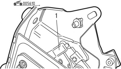
Figure 6.10. Clutch pedal cap: 1 - cap
- remove cap 1 (figure 6.10) from the clutch pedal.
Install the clutch drive cable in the following order:
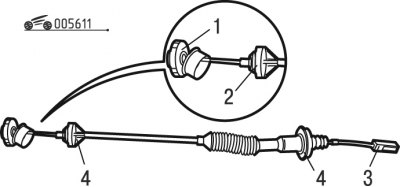
Figure 6.11. Clutch cable: 1 - washer; 2, 4 - bushings; 3 - cap
- lubricate the pressing surface of washer 1 (figure 6.11) with consistent grease;
- fill cap 3 with grease;
- fill bushings 2 and 4 with tire mounting paste;
- continue installing the cable in the reverse order of removal.