
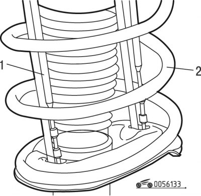
Pic. 6.133. Installation of rods to hold the spring: 1 - thrust; 2 - spring
- install on both sides of the car traction 1 (see fig. 6.133), holding springs 2 of the shock absorber strut;
- loosen the tightening torque of the front wheel mounting bolts;
- raise the car on a lift and remove the front wheels;
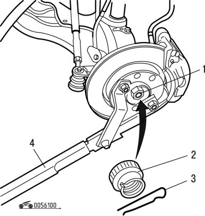
Pic. 6.140. Unscrewing the wheel drive nut: 1 - nut; 2 - locking sleeve; 3 - cotter pin; 4 - fixture
- remove cotter pin 3 (pic. 6.140) and locking sleeve 2;
- lock the wheel hub using tool 4 and unscrew nut 1;
- drain the oil from the gearbox;
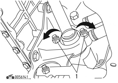
Pic. 6.141. Mounting of the intermediate support: 1 - nuts
- on the right side unscrew the nuts 1 (pic. 6.141) and turn the bolts 90°;
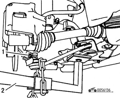
Pic. 6.136. Disconnecting the ball joint from the steering knuckle: 1 - bolt; 2 - fixture
- unscrew bolt 1 (see fig. 6.136) ball joint mountings;
- remove the ball joint using tool 2, fixing the lower arm in the lower position;
- turn the wheels to the right until they stop;
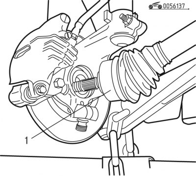
Pic. 6.137. Removing the wheel drive: 1 - outer CV joint
- remove the splined shank of the outer joint 1 (see fig. 6.137) from the wheel hub and remove the wheel drive shaft from the gearbox;
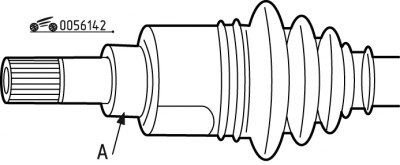
Pic. 6.142. Protection of the bearing surface under the stuffing box
- protect the bearing surfaces A with adhesive tape (pic. 6.142) oil seals at the outlet of the gearbox;
- repeat similar operations on the left side, with the exception of operations with an intermediate support, turning the wheels all the way to the left;
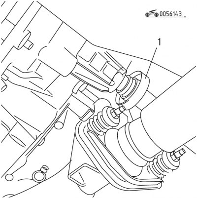
Pic. 6.143. Removing the mud deflector: 1 - mud deflector
- remove the mud deflector 1 (pic. 6.143).
Install the front wheel drive in the following order:
- check the absence of backlash in the hinges, the condition of the mudguards, the condition of the support bearing;
- clean and lubricate with TOTAL 3945 grease the splines of the wheel hub and the splines of the outer joint shank;
- lubricate the bearing outer race and its seat in the lower right engine mount with TOTAL 3945 grease;
- replace oil seals at the outlet of the gearbox;
- fill the space between the lips of the oil seals with grease;
- on the right side, insert the inner joint shank into the differential;
- install the splined shank of the outer joint into the wheel hub;
- fix the ball joint on the steering knuckle by tightening the bolt 1 (see fig. 6.136) torque 40 Nm;
- pre-tighten one of the nuts 1 (see fig. 6.141) torque 7 Nm;
- tighten the other nut with a torque of 13.5 Nm;
- finally tighten the first nut with a torque of 13.5 Nm;
- lubricate the end face and threads of nut 1 with MOLIKOTE D321R grease (see fig. 6.140);
- tighten nut 1 without cotter pin to 245 Nm, and nut with cotter pin to 325 Nm;
- install the locking sleeve 2 and fix it with cotter pin 3;
- carry out similar work on installing the wheel drive on the left side, excluding work related to the intermediate support;
- install the wheels by tightening the mounting bolts with a torque of 85 Nm;
- fill the gearbox with oil and check the level.