
English Русский
Български
Беларускі
Український
Српски
Hrvatski
Română
Polski
Slovenský
Magyar
Bookmark Articles Sitemap Contacts
Company Hyundai Company Opel Company Skoda Company Kia Company Mitsubishi Company LADA Company Audi
PeugeotBook.ru


Series 100   Series 200   Series 300   400-500   Series 600   Crossovers   Others
 
Partner I (1996-2008) Peugeot 807 (2002-2014) Peugeot 806 (1994-2002) Peugeot J5 (1981-1993)

Coolant — draining and filling (Peugeot Eurovans 806)

  • Main
  • Пежо
  • Peugeot 806 (1994-2002)
  • Power unit
  • Cooling system
  • Coolant — draining and filling
0
Filling the coolant is not a simple matter of pouring fluid into the expansion tank. Some of the hoses that carry coolant are located above the expansion tank. For this reason, the coolant is added using a special container to avoid the formation of air locks in the system.

The cooling system has two drain holes closed with threaded plugs. When draining fluid from the system, these holes must be open.
1. Remove the cap from the expansion tank, then unscrew the drain plug at the bottom of the radiator. As a rule, the expansion tank and cap are located in the engine compartment as shown in Illustration 2.1.
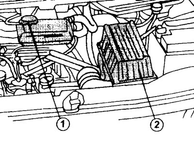
2.1 Remove cap 1 from the expansion tank when draining the fluid from the cooling system. 2 - air…

2.1 Remove cap 1 from the expansion tank when draining the fluid from the cooling system. 2 - air filter


And only cars with an XU engine and air conditioning have a different location of the expansion tank. On the drain pipe of some cars, next to the drain hole, there is an opportunity to connect a hose, which allows for a more accurate draining of the liquid directly into a container (see illustration 2.1a).
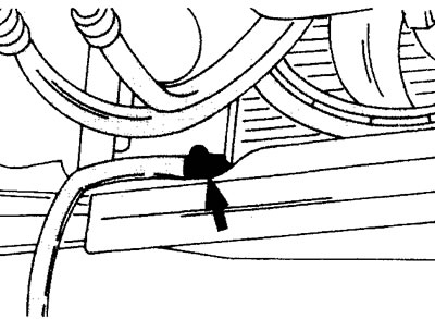
2.1a Drain nipple for connecting a hose to drain the coolant from the system

2.1a Drain nipple for connecting a hose to drain the coolant from the system


Caution! Do not remove the expansion tank cap when the engine is hot.


If the coolant is being drained for replacement, it is recommended to disconnect the lower radiator hose.

2. Remove the engine splash guard

3. Unscrew the drain plug on the cylinder block near the flywheel (see illustration).
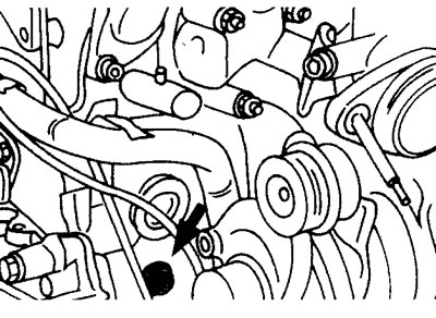
2.3 Unscrew the drain plug on the cylinder block near the flywheel. This drain hole may be located…

2.3 Unscrew the drain plug on the cylinder block near the flywheel. This drain hole may be located in a different location on other engines. The illustration shows a 1.9L diesel engine


4. Remove the air vent plugs, referring to the corresponding diagrams (see above). On XU engines, one air vent is located on the right side of the cylinder block next to the air filter, and the second is near the right side of the air filter (see illustration 2.4).
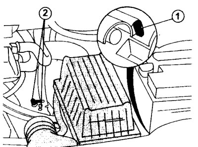
2.4 Ventilation openings 1 and 2 of the XU engine cooling system.

2.4 Ventilation openings 1 and 2 of the XU engine cooling system.


For vehicles with a².0 liter engine without air conditioning, the vent is located on the hose itself where it connects.

On 16-valve engines, the corresponding vents are located at the right end of the hoses. In addition, there is a vent on the radiator. Diesel engines have only one vent, located at point 1 (see illustration 2.4).

5. Flush the coolant circulation system if it has not been drained for a long time. To do this, insert the hose into the radiator neck, connecting the other end of the hose to the water tap. Flush the system until clear water comes out of the drain and vent holes.

6. Prepare a mixture whose frost resistance corresponds to the air temperature at the given time. A mixture of 35% antifreeze and 65% water is suitable for normal subzero temperatures (down to -15°C). A coolant consisting of 50% antifreeze and 50% water provides system protection at temperatures down to -35°C. When purchasing antifreeze, follow the engine manufacturer's instructions.

7. Screw the plugs into the drain holes or connect the lower radiator hose. Tighten the threaded plugs in the cylinder block to a torque of 25 Nm. The plugs are fitted with sealing gaskets to ensure a tight seal. As previously mentioned, a special container is used to fill the coolant; it screws onto the neck of the expansion tank instead of the cap (see illustration 2.7).
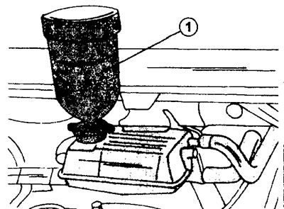
2.7 To fill the coolant, use a special container that is screwed onto the neck of the expansion…

2.7 To fill the coolant, use a special container that is screwed onto the neck of the expansion tank instead of the cap


On engines with 16 valves, the container is inserted into the neck of the tank. A container connected in this way forms a single unit with the expansion tank, and the liquid level in this case is higher than even highly secured hoses. As a result, the cooling system can be filled completely without fear of air locks.

8. Pour liquid until it starts to flow out of the vent hole continuously. Screw in and tighten the vent plug.

9. Make sure the coolant reservoir is full and bleed the engine. After starting the engine, increase its speed, keeping it within 1500-2000 rpm, waiting for the radiator fan to turn on and off. After this, turn off the engine.

10. Remove the coolant filling container.

Caution! The coolant remaining in the container may be hot. Some coolant will leak out, but the system will be full.


11. Screw the cap onto the neck of the expansion tank of a car with a gasoline engine. Make sure the drain and vent plugs are screwed in and tightened. The engine must not be started if the plugs are not tightly tightened.

12. Turn off the diesel engine and allow the coolant to cool down (in about 3 hours). Check the fluid level in the expansion tank and close it with the cap. The coolant level in the reservoir should be at the "Max" mark (see illustration).
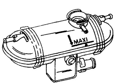
2.12 Coolant reservoir. When the engine is cold, the coolant level should be level with the «Max»…

2.12 Coolant reservoir. When the engine is cold, the coolant level should be level with the "Max" mark


Otherwise, add coolant and tighten the cap to the second notch.

13. Reinstall the engine splash guard.
This article is available at russian, bulgarian, belarusian, ukrainian, serbian, croatian, romanian, polish, slovak, hungarian
Article reviewed by editor: Shirokov Arseny
Share information:
Previous
Peugeot 806: Cooling system
Next

General description and precautions
Cooling system specifications
Radiator — removal and installation
Water pump — removal and installation
Removal the thermostat
Cooling liquid
Checking thermal switches
See similar information for other Peugeot models

➨ Coolant renewal Peugeot 106 (1991-2003)
➨ Draining and filling coolant Peugeot 206 (1998-2012)
➨ Draining and filling coolant Peugeot 306 (1993-2002)
➨ Draining the coolant Peugeot 405 (1987-1997)
➨ Coolant Temperature Sensor — Removal and Installation Peugeot 605 (1989-2000)
Link to this article in different formats
Comments and feedback from visitors
No comments yet


Add two numbers 34 + 32


Partner I (1996-2008) 
  • General information
  • Introduction to the guide
  • Faults en route
  • Weekly checks
  • User manual
  • Maintenance (petrol)
  • Maintenance (diesel)
  • Power unit
  • Petrol engines
  • Diesel engines «XUD»
  • Diesel engines «DW»
  • Overhaul of petrol engines
  • Overhaul of diesel engines
  • Cooling and heating
  • Power and exhaust (petrol)
  • Power and exhaust (XUD diesels)
  • Power and exhaust (DW diesels)
  • Emission reduction
  • Starting and charging system
  • Transmission
  • Clutch
  • Mechanical gearbox
  • Drive shafts
  • Chassis, running gear
  • Brake system
  • Car suspension
  • Steering
  • Body and interior
  • Exterior (external elements)
  • Interior (internal elements)
  • Doors, locks and windows
  • Electrical equipment
  • Equipment and devices
  • Electrical circuits
Peugeot 807 (2002-2014) 
  • General information
  • Operating instructions
  • Maintenance
  • Troubleshooting
  • Power unit
  • Gasoline engines
  • Diesel engines
  • Cooling and heating
  • Fuel injection (petrol)
  • Fuel system (diesel)
  • Fuel system
  • Exhaust system
  • Ignition system
  • Transmission
  • Clutch
  • Manual gearbox
  • Automatic gearbox
  • Chassis, running gear
  • Brake system
  • Car suspension
  • Steering system
  • Body and interior
  • Exterior (external elements)
  • Interior (internal elements)
  • Electrical equipment
  • Power devices
  • Electrical circuits
Peugeot 806 (1994-2002) 
  • General information
  • User manual
  • Maintenance
  • Power unit
  • Petrol engines
  • Diesel engines
  • Lubrication system
  • Cooling system
  • Fuel injection (petrol)
  • Fuel system (diesel)
  • Ignition and exhaust systems
  • ECM Bosch Motronic MP 3.2
  • ECM Magneti-Marelli (MM)
  • Transmission
  • Clutch
  • Mechanical gearbox
  • Chassis, running gear
  • Brake system
  • Car suspension
  • Steering
  • Electrical equipment
  • Equipment and devices
  • Electrical circuits
Peugeot J5 (1981-1993) 
  • General information
  • Introduction to manual
  • Specifications
  • Gasoline engine
  • Engine repair
  • Lubrication system
  • Cooling system
  • Fuel system
  • Ignition system
  • Diesel engine
  • Engine repair (DB9)
  • Lubrication system (DB9)
  • Cooling system (DB9)
  • Fuel injection (DB9)
  • Engine repair (U25)
  • Lubrication system (U25)
  • Cooling system (U25)
  • Fuel injection (U25)
  • Transmission
  • Clutch
  • Gearbox
  • Drive shafts
  • Chassis, running gear
  • Steering system
  • Car suspension
  • Brake system
  • Electrical equipment
  • Power devices
  • Electrical circuits
PeugeotBook.ru © 2018–2026 | Mobile version | Sitemap: EN BG BY UA RS HR RO PL SK HU | Write message | Site search | Add to bookmarks | Peugeot owners
106 (1991-2003) | 206 (1998-2012) | 207 (2006-2014) | 305 (1977-1989) | 306 (1993-2002) | 307 (2001-2008) | 405 (1987-1997) | 406 (1995-2004) | 605 (1989-2000) | Partner-I (1996-2008) | Eurovans-807 (2002-2014) | Eurovans-806 (1994-2002) | J5 (1981-1993) |
Cookies are used to ensure the correct display of pages on the site.