
English Русский
Български
Беларускі
Український
Српски
Hrvatski
Română
Polski
Slovenský
Magyar
Bookmark Articles Sitemap Contacts
Company Hyundai Company Opel Company Skoda Company Kia Company Mitsubishi Company LADA Company Audi
PeugeotBook.ru


Series 100   Series 200   Series 300   400-500   Series 600   Crossovers   Others
 
Partner I (1996-2008) Peugeot 807 (2002-2014) Peugeot 806 (1994-2002) Peugeot J5 (1981-1993)

General description and precautions (Peugeot Eurovans 806)

  • Main
  • Пежо
  • Peugeot 806 (1994-2002)
  • Power unit
  • Cooling system
  • General description and precautions
0
The liquid circulating in the cooling system removes heat from the engine, cooling in the radiator and also heating the interior. The coolant used is a product with anti-corrosion and frost-protective properties.

Forced circulation of the coolant is achieved by means of a water pump, which is driven by the timing belt. The water pump forces coolant into a fairly large number of channels and hoses.

Cooling of the heated liquid is provided by a radiator with a sufficiently large liquid distribution area. Cooling of the liquid in the radiator occurs due to the oncoming air flowing around the cooling fins of the radiator. When the engine load increases and, accordingly, heat transfer increases, the liquid is additionally cooled by an electric radiator fan. On vehicles with diesel engines, as well as those equipped with air conditioning, two fans are installed. The radiator fan is switched on by a thermal switch located on the bottom of the radiator.

To ensure that the coolant quickly reaches the required operating temperature, the cooling system is divided into small and large circuits. The large coolant circulation circuit is activated by a thermostat, which is a thermoelement filled with wax and equipped with a spring that ensures the necessary movement of the valve plates, thereby opening or closing the large circuit.

During the engine warm-up period, a valve controlled by a thermostat closes the access of coolant to the radiator. The bypass valve immediately directs the flow of coolant to the water pump, which forces coolant into the engine cooling jacket. Circulation of coolant in such a circuit promotes rapid warming up of the engine.


As soon as the coolant temperature rises to 85-100°C, the thermostat gradually opens the large circuit valve, directing the liquid into the radiator. The cold liquid from the radiator mixes with the hot liquid from the engine, and only after this does the liquid again enter the engine cooling jacket. This way the hot engine is not exposed to cold coolant.

To increase the cooling effect, as the coolant heats up, increased pressure, reaching almost 1.0 bar, is created in the cooling system. This pressure is maintained by a corresponding valve in the expansion tank cap. Increased pressure in the system increases the boiling point of the coolant. When the permissible pressure level in the system is exceeded, the release valve on the expansion tank cap opens and the excess pressure is released.

Over time, the anti-corrosion effect of the coolant decreases, so the coolant itself must be replaced with a new one.

The cooling circuit of vehicles with diesel engines includes an oil cooler, installed between the oil filter and the cylinder block. The oil radiator is connected to the cooling system by two hoses. A diesel fuel heater unit is located on the coolant outlet pipe, which facilitates starting the diesel engine in cold weather.

Caution! The radiator fan may turn on even when the engine is off. This is especially possible immediately after turning off the engine. For this reason, care must be taken when working in the engine compartment near the fan.
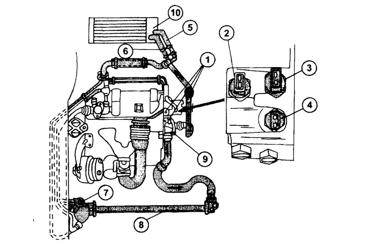

1.0 Cooling system diagram of the XU7 1.8 liter engine or the XU10J engine without air conditioning

1.0 Cooling system diagram of the XU7 1.8 liter engine or the XU10J engine without air conditioning
1 - ventilation plugs
2 - coolant temperature sensor
3 - thermal switch
4 - coolant temperature sensor
5 - heater radiator supply hose
6 - heater radiator outlet hose
7 - expansion tank
8 - radiator and radiator fan
9 - thermostat
10 - heater radiator
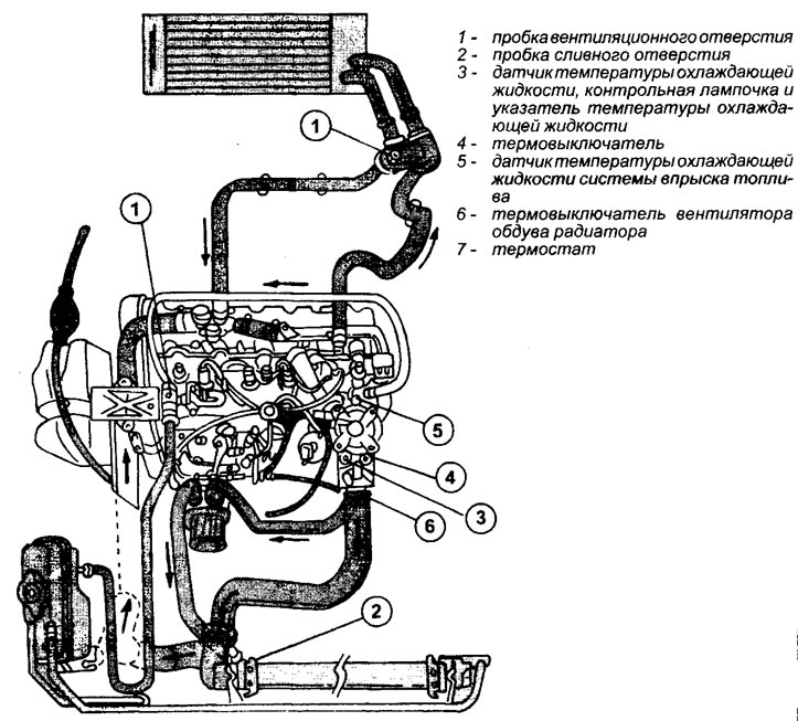


1.0a Coolant circuit of a 1.9L turbocharged diesel engine

1.0a Coolant circuit of a 1.9L turbocharged diesel engine


(The source is located on the website PEUGEOTBOOK)
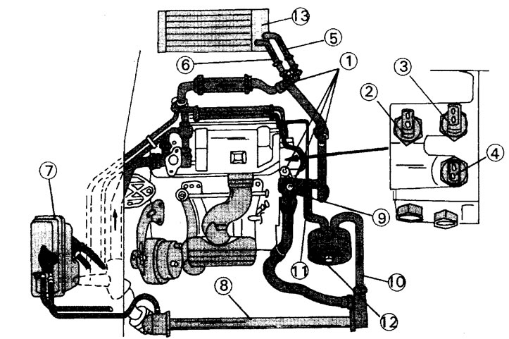
1.0b Coolant circulation circuit of a vehicle with a 2.0L engine and automatic transmission

1.0b Coolant circulation circuit of a vehicle with a 2.0L engine and automatic transmission
1 - ventilation plugs
2 - thermal switch
3 - thermal switch
4 - coolant temperature sensor
5 - heater radiator supply hose
6 - heater radiator outlet hose
7 - expansion tank
8 - radiator and radiator fan
9 - thermostat
10 - oil radiator outlet hose
11 - Oil radiator feed hose
12 - oil radiator
13 - heater radiator
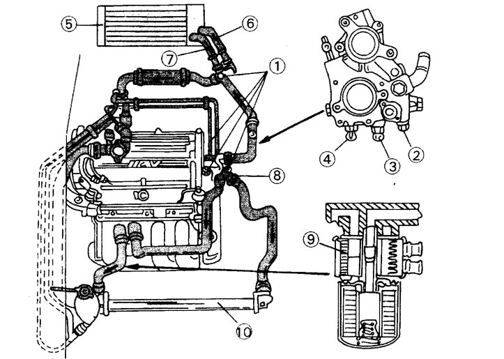

1.0v Cooling system diagram for a 2.0-liter, 16-valve gasoline engine

1.0v Cooling system diagram for a 2.0-liter, 16-valve gasoline engine
1 - ventilation plugs
2 - thermal switch
3 - thermal switch
4 - coolant temperature sensor
5 - heater radiator
6 - heater radiator supply hose
7 - heater radiator outlet hose
8 - thermostat
9 - oil radiator
10- radiator and radiator fan
This article is available at russian, bulgarian, belarusian, ukrainian, serbian, croatian, romanian, polish, slovak, hungarian
Article reviewed by editor: Shirokov Arseny
Share information:
Previous
Peugeot 806: Cooling system
Next

Cooling system specifications
Coolant — draining and filling
Radiator — removal and installation
Water pump — removal and installation
Removal the thermostat
Cooling liquid
See similar information for other Peugeot models

➨ General information and precautions Peugeot 106 (1991-2003)
➨ General information about the ignition system of the TU5 petrol… Peugeot 207 (2006-2014)
➨ General description of the Peugeot 305 Peugeot 305 (1977-1989)
➨ Catalyst — General Information Peugeot 405 (1987-1997)
➨ Fuel System — General Information and Precautions Peugeot 605 (1989-2000)
Link to this article in different formats
Comments and feedback from visitors
No comments yet


Add two numbers 49 + 38


Partner I (1996-2008) 
  • General information
  • Introduction to the guide
  • Faults en route
  • Weekly checks
  • User manual
  • Maintenance (petrol)
  • Maintenance (diesel)
  • Power unit
  • Petrol engines
  • Diesel engines «XUD»
  • Diesel engines «DW»
  • Overhaul of petrol engines
  • Overhaul of diesel engines
  • Cooling and heating
  • Power and exhaust (petrol)
  • Power and exhaust (XUD diesels)
  • Power and exhaust (DW diesels)
  • Emission reduction
  • Starting and charging system
  • Transmission
  • Clutch
  • Mechanical gearbox
  • Drive shafts
  • Chassis, running gear
  • Brake system
  • Car suspension
  • Steering
  • Body and interior
  • Exterior (external elements)
  • Interior (internal elements)
  • Doors, locks and windows
  • Electrical equipment
  • Equipment and devices
  • Electrical circuits
Peugeot 807 (2002-2014) 
  • General information
  • Operating instructions
  • Maintenance
  • Troubleshooting
  • Power unit
  • Gasoline engines
  • Diesel engines
  • Cooling and heating
  • Fuel injection (petrol)
  • Fuel system (diesel)
  • Fuel system
  • Exhaust system
  • Ignition system
  • Transmission
  • Clutch
  • Manual gearbox
  • Automatic gearbox
  • Chassis, running gear
  • Brake system
  • Car suspension
  • Steering system
  • Body and interior
  • Exterior (external elements)
  • Interior (internal elements)
  • Electrical equipment
  • Power devices
  • Electrical circuits
Peugeot 806 (1994-2002) 
  • General information
  • User manual
  • Maintenance
  • Power unit
  • Petrol engines
  • Diesel engines
  • Lubrication system
  • Cooling system
  • Fuel injection (petrol)
  • Fuel system (diesel)
  • Ignition and exhaust systems
  • ECM Bosch Motronic MP 3.2
  • ECM Magneti-Marelli (MM)
  • Transmission
  • Clutch
  • Mechanical gearbox
  • Chassis, running gear
  • Brake system
  • Car suspension
  • Steering
  • Electrical equipment
  • Equipment and devices
  • Electrical circuits
Peugeot J5 (1981-1993) 
  • General information
  • Introduction to manual
  • Specifications
  • Gasoline engine
  • Engine repair
  • Lubrication system
  • Cooling system
  • Fuel system
  • Ignition system
  • Diesel engine
  • Engine repair (DB9)
  • Lubrication system (DB9)
  • Cooling system (DB9)
  • Fuel injection (DB9)
  • Engine repair (U25)
  • Lubrication system (U25)
  • Cooling system (U25)
  • Fuel injection (U25)
  • Transmission
  • Clutch
  • Gearbox
  • Drive shafts
  • Chassis, running gear
  • Steering system
  • Car suspension
  • Brake system
  • Electrical equipment
  • Power devices
  • Electrical circuits
PeugeotBook.ru © 2018–2026 | Mobile version | Sitemap: EN BG BY UA RS HR RO PL SK HU | Write message | Site search | Add to bookmarks | Peugeot owners
106 (1991-2003) | 206 (1998-2012) | 207 (2006-2014) | 305 (1977-1989) | 306 (1993-2002) | 307 (2001-2008) | 405 (1987-1997) | 406 (1995-2004) | 605 (1989-2000) | Partner-I (1996-2008) | Eurovans-807 (2002-2014) | Eurovans-806 (1994-2002) | J5 (1981-1993) |
Cookies are used to ensure the correct display of pages on the site.