



Table of contents: General information 🠇 Precautions 🠇
General information
The cooling system is of pressurised type, comprising a coolant pump driven by the timing belt, an aluminium crossflow radiator, with integral expansion tank on petrol models, electric cooling fan, a thermostat, heater matrix and all associated hoses and switches. A separate remotely-mounted coolant expansion tank is fitted to diesel models (see illustrations).
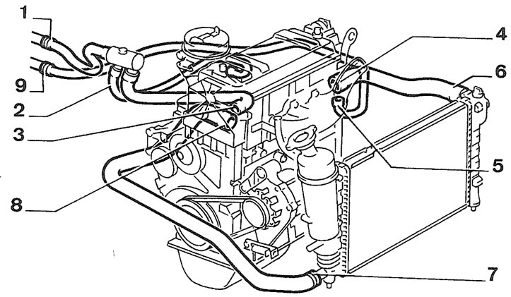
1.1a. Typical cooling system layout - petrol engine 1. Heater matrix outlet; 2. Heater return to carburettor/throttle body; 3. Heater return to engine; 4. Engine outlet; 5. Engine outlet to heater matrix; 6. Radiator inlet; 7. Radiator outlet; 8. Engine inlet; 9. Heater matrix inlet
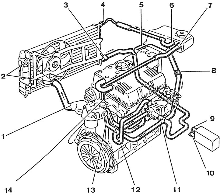
1.1b. Typical cooling system layout - diesel engine 1. Engine outlet; 2. Radiator inlet; 3. Radiator outlet; 4. Radiator-to-expansion tank hose; 5. Expansion tank-to-engine hose; 6. Expansion tank-to-radiator hose; 7. Expansion tank inlet; 8. Bleed screw; 9. Heater matrix outlet; 10. Heater matrix inlet; 11. Engine inlet; 12. By-pass outlet to heater matrix; 13. By-pass outlet to engine
The system functions as follows. Cold coolant in the bottom of the radiator passes through the bottom hose to the coolant pump, where it is pumped around the cylinder block and head passages and through the oil cooler (where fitted). After cooling the cylinder bores, combustion surfaces and valve seats, the coolant reaches the underside of the thermostat, which is initially closed. The coolant passes through the heater and is returned via the cylinder block to the coolant pump.
When the engine is cold, the coolant circulates only through the cylinder block, cylinder head and heater. When the coolant reaches a predetermined temperature, the thermostat opens and the coolant passes through the top hose to the radiator. As the coolant circulates through the radiator, it is cooled by the inrush of air when the car is in forward motion. The airflow is supplemented by the action of the electric cooling fan when necessary. Upon reaching the bottom of the radiator, the coolant has now cooled and the cycle is repeated.
When the engine is at normal operating temperature, the coolant expands and some of it is displaced into the expansion tank. Coolant collects in the tank and is returned to the radiator when the system cools.
On some models, the coolant is also passed through the engine oil cooler and, where fitted, the automatic transmission heat exchanger.
The electric cooling fan mounted in front of the radiator are controlled by a thermostatic switch. At a predetermined coolant temperature, the switch/sensor actuates the fan.
Precautions
Warning: Do not attempt to remove the expansion tank filler cap, or to disturb any part of the cooling system, while the engine is hot, as there is a high risk of scalding. If the expansion tank filler cap must be removed before the engine and radiator have fully cooled (even though this is not recommended), the pressure in the cooling system must first be relieved. Cover the cap with a thick layer of cloth, to avoid scalding and slowly unscrew the filler cap until a hissing sound is heard. When the hissing has stopped, indicating that the pressure has reduced, slowly unscrew the filler cap until it can be removed; if more hissing sounds are heard, wait until they have stopped before unscrewing the cap completely. At all times, keep well away from the filler cap opening and protect your hands.
Warning: Do not allow antifreeze to come into contact with your skin, or with the painted surfaces of the vehicle. Rinse off spills immediately, with plenty of water. Never leave antifreeze lying around in an open container, or in a puddle in the driveway or on the garage floor. Children and pets are attracted by its sweet smell, but antifreeze can be fatal if ingested.
(Information copied from the resource: «peugeotbook.ru»)
Warning: If the engine is hot, the electric cooling fan may start rotating even if the engine is not running. Be careful to keep your hands, hair and any loose clothing well clear when working in the engine compartment.
Warning: Refer to Section 10 for precautions to be observed when working on models with air conditioning.