



When replacing the timing belt, the front right wheel must be raised.
- Loosen the nuts on the right front wheel, lift the front wheel with a jack and place a stand under the body. Remove the wheel.
- Unscrew the mudguard from the wheel arch.
- Loosen the tension and remove the drive belt of the units.
- Using Figure 274, remove the timing belt covers. In this case, first push the upper casing forward and then pull it upward. Pay attention to the inserted spacer bushings.
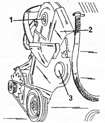
Figure 274. The front side of the engine is covered by three casings 1, 2 and 3.
- Engage a higher gear and turn the hub of the raised front wheel until the piston of the first cylinder is in the top dead center position of the compression stroke. In this position, insert the flywheel locking rod.
- Prepare two M8x40 bolts. Insert one bolt into the camshaft toothed pulley at location (1) in Figure 275, and the other bolt into the high-pressure fuel pump drive gear at location (2). In this case, the gas distribution mechanism is blocked.
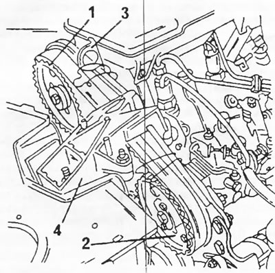
Figure 275 Removing the timing belt. 1. Timing pulley of the camshaft; 2. Toothed pulley of the high-pressure fuel pump; 3. Engine lifting bracket; 4. Engine mount
- Loosen the bolt (2) and nut (1) of the toothed belt tension roller in Figure 276. Insert into the square hole (6) on figure 225 extension with a square rod 9.52 mm (and ratchet), to compress the spring of the automatic timing belt tensioner. The tetrahedron is available in a set of key heads with a 3/8-inch adapter. Crank the extension cable several times using the ratchet. Tighten the bolt (2) in Fig. 276 to secure the tensioner in the new position.
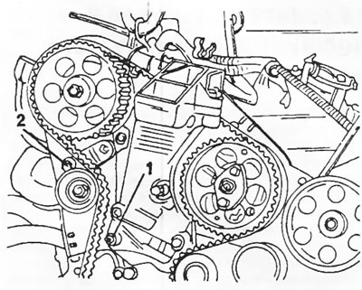
Figure 276. The automatic toothed belt tensioner is secured with a nut (1) and bolt (2).
- Unscrew the flywheel housing and lock the flywheel or crankshaft in a certain way by engaging a high gear.
- Loosen the crankshaft pulley bolt and remove the pulley. To do this, support it with two crowbars or use a puller.
- Attach a cable or chain to the engine lifting bracket (3) in Figure 275 and hang the engine using a pulley block or other lifting mechanism. You can also place a jack under the engine and carefully lift the engine on its mount.
- Remove the engine mount (4) in Fig. 275.
- Remove the timing belt. First, the belt is removed from the camshaft toothed pulley.
- After this, all other parts of the valve timing mechanism can be replaced as necessary.
- Installation of the valve timing mechanism parts is carried out as follows. The description contains links to previously provided drawings.
- Check that all parts in contact with the timing belt are free of oil and grease.
- Three locking bolts or pins must be inserted. Otherwise, turn the camshaft timing pulley until one of the M8 bolts takes position (1) in Figure 275. This sets the timing pulley to the position required for installing the timing belt.
- Tighten the timing belt tensioner bolt (2) to a torque of 20 Nm (Figure 276).
- Check that the timing belt tension roller is fully pressed outward, i.e. secured in this position. Both timing belt rollers must rotate freely and not jam.
- By inserting two M8 bolts (2) in Fig. 275, lock the drive gear of the high-pressure fuel pump. In this case, the fuel pump is in the position of the injection moment of the first cylinder.
- Lock the crankshaft at top dead center by inserting the locking rod from the rear into the flywheel as shown in Figure 246.
- Apply the timing belt. First place the belt on the crankshaft toothed pulley, then on the rigidly fixed guide roller (5) in Figure 260, on the high-pressure fuel pump toothed pulley (6) and on the camshaft toothed pulley (2). Then, having tensioned the belt, place it on the other side on the water pump pulley (8) and finally on the tension roller (9).
- Check the engagement of the timing belt teeth with all toothed pulleys.
- Screw the bolt with the washer into the end of the crankshaft and temporarily tighten the bolt.
- To release the tension roller, loosen the bolt (1) and nut (2).
- Remove all locking bolts.
- To align the position of the timing belt, turn the crankshaft in the working direction of rotation for at least two revolutions without interruption or changing the direction of rotation.
- Loosen the bolt and nut again in Figure 276. This will set the tension roller to the belt tensioning position. In this position, tighten the bolt (1) and nut (2) to a torque of 18 Nm.
- Turn the engine over a few revolutions and reinsert the timing drive lock bolts. If the bolts are difficult to insert, the valve timing is out of adjustment and must be adjusted again.
- Remove the bolt and washer from the crankshaft.
- Install three timing belt covers.
- Place the crankshaft toothed pulley on and tighten the bolt with the washer. Coat the bolt threads with Loctite.
- While holding the crankshaft from turning, tighten the timing pulley to a torque of 40 Nm. From this position, tighten the bolt an additional 60°.
- All other work is carried out in reverse order. Secure the engine mount by tightening the bolts to a torque of 45 Nm. Don't forget to install the clutch pressure plate cover.