
English Русский
Български
Беларускі
Український
Српски
Hrvatski
Română
Polski
Slovenský
Magyar
Bookmark Articles Sitemap Contacts
Company Hyundai Company Opel Company Skoda Company Kia Company Mitsubishi Company LADA Company Audi
PeugeotBook.ru


Series 100   Series 200   Series 300   400-500   Series 600   Crossovers   Others
 
Partner I (1996-2008) Peugeot 807 (2002-2014) Peugeot 806 (1994-2002) Peugeot J5 (1981-1993)

Gas distribution mechanism drive (Peugeot J5)

  • Main
  • Пежо
  • Peugeot J5 (1981-1993)
  • Gasoline engine
  • Engine repair
  • Gas distribution mechanism drive
0
The timing mechanism is driven by a drive chain, the tension of which is regulated by a tensioner. The chain and both sprockets can be replaced without removing the engine. These works are described below.
  • Remove the timing cover as described in section 2.7.4.
  • Drain the oil from the engine and remove the oil pan.
  • Remove the chain tensioner. There are differences, however, as there are two designs of tensioning devices.

Sedis chain tensioner


Insert a screwdriver into the hole shown in Figure 29 and press the clamp until it comes off. After this, turn the screwdriver in the direction of the arrow. This locks the ratchet mechanism located below and the chain tensioner remains in a free position.

Renold chain tensioner


This tensioner does not have a self-locking feature, meaning it must be mechanically locked before being removed from the cylinder block. This requires a piece of wire that is placed around the chain tensioner according to figure 30. Tighten the ends of the wire so that the clamp cannot release from the tensioner.

With all tensioning devices


  • Unscrew the two mounting bolts and remove the chain tensioner. The tensioner must be handled with care to ensure that its locking mechanism is not disturbed. There is a rod filter located under the chain tensioner, which should be removed immediately.
  • In the order listed, remove the camshaft sprocket, crankshaft sprocket and camshaft. The camshaft sprocket is secured with a bar and three bolts.

Caution: The timing chain does not have installation markings. Therefore, before removal, in case of reinstallation, the chain and both sprockets must be marked with a paint line to ensure their subsequent installation in their previous relative positions.


  • If necessary, you can unscrew the rear timing plate.

Check all timing drive components. The chain sprocket teeth or chain rollers may be damaged or worn. Clean the filter thoroughly.

Installation of the timing drive components is carried out as follows:
  • Place a new paper gasket on the cylinder block and screw the board to the block. Tighten the bolts to a torque of 10 Nm.
  • Place the chain sprocket onto the crankshaft from the front side. The key should fit into the groove, and the ignition timing mark should be located on the outside.
  • Turn the crankshaft and camshaft so that the marks on both sprockets are located opposite each other. This is a very important work operation. After the stars have been placed, their relative positions should be compared with Figure 86.
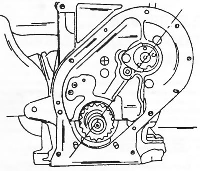
Figure 86. Turn the crankshaft and camshaft until the ignition timing marks are aligned opposite…

Figure 86. Turn the crankshaft and camshaft until the ignition timing marks are aligned opposite each other.

  • Place the chain on the crankshaft sprocket and insert the sprocket into the chain from the other side. Check that the marks are positioned as shown in Figure 87 and secure the sprocket to the camshaft. If the marks on the chain are not visible, the chain should be applied in accordance with the markings made during removal.
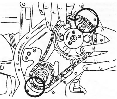
Figure 87. When applying the drive chain, ensure the correct positioning of the ignition timing…

Figure 87. When applying the drive chain, ensure the correct positioning of the ignition timing marks.


  • Place a new locking plate on the camshaft sprocket, install the three bolts and tighten the bolts to 23 Nm (Figure 88). Hammer the lock plate around the bolt heads.
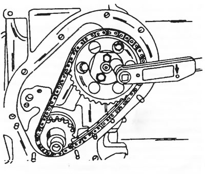
Figure 88. The camshaft sprocket is secured to the shaft with three locking bolts.

Figure 88. The camshaft sprocket is secured to the shaft with three locking bolts.

  • After following the above instructions for disassembling and assembling the tensioner, install the chain tensioner.
  • Screw on the timing cover with a new gasket. In this case, the cover must be precisely centered, since the seal still needs to be pressed in. A piece of tube is used to press in the seal lubricated with engine oil. Place the oil seal on the timing cover, attach the tube and screw the large belt pulley nut onto the shaft. Under the pressure of the tube, the seal is pressed in. Tighten the cover bolts to 13 Nm.
  • Drive a key into the crankshaft and drive the belt pulley onto the key and shaft. Block the crankshaft with a piece of wood in the crankcase and tighten the nut to a torque of 170 Nm.
  • If the plate with the ignition timing scale has been unscrewed, it should be adjusted to determine the position of the top dead center.
  • Turn the engine until the pistons of the first and fourth cylinders reach the exact position of top dead center, while the valves of the fourth cylinder should be in the switching phase, that is, one of the valves should open and the other should close. The exact position of the top dead center is determined using a dial indicator, which is positioned as shown in Figure 50.
  • Screw on the plate with the indicator for setting the ignition timing so that the "zero" on the plate is located opposite the mark on the crankshaft belt pulley. Tighten both plate mounting nuts. Mark one of the nuts with paint (for subsequent purposes).
  • All other work is carried out in reverse order.
This article is available at russian, bulgarian, belarusian, ukrainian, serbian, croatian, romanian, polish, slovak, hungarian
Article reviewed by editor: Bespalov Alexey
Share information:
Previous
Peugeot J5: Engine repair
Next

Crankshaft and crankshaft bearings
Cylinder block
Pistons and connecting rods
Cylinder head
Engine assembly
Compression check
See similar information for other Peugeot models

➨ Clutch adjustment check and control mechanism lubrication Peugeot 106 (1991-2003)
➨ Drive mechanism — general information Peugeot 207 (2006-2014)
➨ Gas distribution mechanism drive Peugeot 306 (1993-2002)
➨ Checking the auxiliary drive belt (10,000 km/6 months) Peugeot 405 (1987-1997)
➨ Timing belt of the gas distribution mechanism drive — removal Peugeot 605 (1989-2000)
Link to this article in different formats
Comments and feedback from visitors
No comments yet


Add two numbers 24 + 24


Partner I (1996-2008) 
  • General information
  • Introduction to the guide
  • Faults en route
  • Weekly checks
  • User manual
  • Maintenance (petrol)
  • Maintenance (diesel)
  • Power unit
  • Petrol engines
  • Diesel engines «XUD»
  • Diesel engines «DW»
  • Overhaul of petrol engines
  • Overhaul of diesel engines
  • Cooling and heating
  • Power and exhaust (petrol)
  • Power and exhaust (XUD diesels)
  • Power and exhaust (DW diesels)
  • Emission reduction
  • Starting and charging system
  • Transmission
  • Clutch
  • Mechanical gearbox
  • Drive shafts
  • Chassis, running gear
  • Brake system
  • Car suspension
  • Steering
  • Body and interior
  • Exterior (external elements)
  • Interior (internal elements)
  • Doors, locks and windows
  • Electrical equipment
  • Equipment and devices
  • Electrical circuits
Peugeot 807 (2002-2014) 
  • General information
  • Operating instructions
  • Maintenance
  • Troubleshooting
  • Power unit
  • Gasoline engines
  • Diesel engines
  • Cooling and heating
  • Fuel injection (petrol)
  • Fuel system (diesel)
  • Fuel system
  • Exhaust system
  • Ignition system
  • Transmission
  • Clutch
  • Manual gearbox
  • Automatic gearbox
  • Chassis, running gear
  • Brake system
  • Car suspension
  • Steering system
  • Body and interior
  • Exterior (external elements)
  • Interior (internal elements)
  • Electrical equipment
  • Power devices
  • Electrical circuits
Peugeot 806 (1994-2002) 
  • General information
  • User manual
  • Maintenance
  • Power unit
  • Petrol engines
  • Diesel engines
  • Lubrication system
  • Cooling system
  • Fuel injection (petrol)
  • Fuel system (diesel)
  • Ignition and exhaust systems
  • ECM Bosch Motronic MP 3.2
  • ECM Magneti-Marelli (MM)
  • Transmission
  • Clutch
  • Mechanical gearbox
  • Chassis, running gear
  • Brake system
  • Car suspension
  • Steering
  • Electrical equipment
  • Equipment and devices
  • Electrical circuits
Peugeot J5 (1981-1993) 
  • General information
  • Introduction to manual
  • Specifications
  • Gasoline engine
  • Engine repair
  • Lubrication system
  • Cooling system
  • Fuel system
  • Ignition system
  • Diesel engine
  • Engine repair (DB9)
  • Lubrication system (DB9)
  • Cooling system (DB9)
  • Fuel injection (DB9)
  • Engine repair (U25)
  • Lubrication system (U25)
  • Cooling system (U25)
  • Fuel injection (U25)
  • Transmission
  • Clutch
  • Gearbox
  • Drive shafts
  • Chassis, running gear
  • Steering system
  • Car suspension
  • Brake system
  • Electrical equipment
  • Power devices
  • Electrical circuits
PeugeotBook.ru © 2018–2026 | Mobile version | Sitemap: EN BG BY UA RS HR RO PL SK HU | Write message | Site search | Add to bookmarks | Peugeot owners
106 (1991-2003) | 206 (1998-2012) | 207 (2006-2014) | 305 (1977-1989) | 306 (1993-2002) | 307 (2001-2008) | 405 (1987-1997) | 406 (1995-2004) | 605 (1989-2000) | Partner-I (1996-2008) | Eurovans-807 (2002-2014) | Eurovans-806 (1994-2002) | J5 (1981-1993) |
Cookies are used to ensure the correct display of pages on the site.