



Table of contents: 2.5.1. Disassembling pistons and…🠇 2.5.2. Checking pistons and…🠇 2.5.3. Assembly of pistons and…🠇
Replacement of pistons and cylinder liners can only be performed with the power unit and gearbox removed. When purchasing new pistons and cylinder liners, be aware that they must be matched to each other in size and must be stored in pairs. This also applies to the case of reinstallation of old parts. In this case, it is necessary to apply the cylinder numbers to the working liners, pistons and connecting rods.
All pistons have two compression rings and one oil scraper ring. The upper compression ring has a chrome plated outer surface, and the second ring has a trapezoidal cross-section. Piston rings have markings that should be on top when installing the rings.
Although pistons and related components are not the same on all engines, this section provides a general description.
When ordering new pistons (and working cylinder liners) it is essential to indicate the engine number.
2.5.1. Disassembling pistons and connecting rods
Disassembling pistons and connecting rods usually does not require special tools, since the piston pins are held in the holes by retaining rings. After removing the retaining rings, the pins are pressed out manually. Remove piston rings using piston ring pliers (Figure 75). If the rings are to be re-installed, they should be marked accordingly. If you don't have piston ring pliers, you can remove the rings by sliding metal plates from opposite sides of the piston under the ring. To avoid scratches, place a plate under the ring joint.
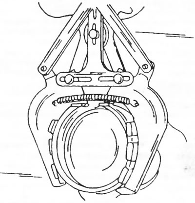
Figure 75. Removing piston rings using special pliers.
2.5.2. Checking pistons and connecting rods
Check all details carefully. If parts show signs of metal corrosion, scratches or wear, they must be replaced.
- Measure the piston ring clearances by height in the piston grooves by successively inserting the rings into the corresponding groove on the piston (Figure 76). The gap is determined by a feeler gauge inserted into the gap between the ring surface and the piston groove surface. If the clearance dimensions do not correspond to the data given in the table of dimensions and adjustments, either the rings or the pistons are worn.
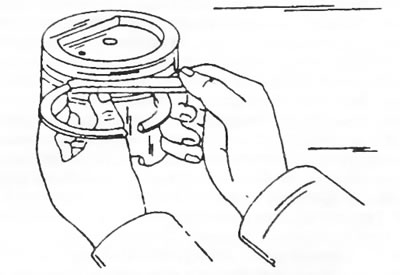
Figure 76. Measuring the piston ring clearance by height in the piston grooves. All grooves must be thoroughly cleaned.
- After this, sequentially insert all piston rings from the top side into the working cylinder liner. Using an inverted piston, push the ring down to a distance of 15 mm from the bottom edge of the hole. To do this, place the cylinder block on its side. To measure the joint gap, insert a feeler gauge into the ring joint. Figure 77 shows how to correctly measure the piston ring joint gap. The joint clearances are not adjustable and if the joint clearances are increased, the piston rings must be replaced.
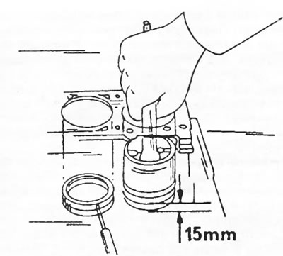
Figure 77. Measuring the piston ring joint gap.
- Measure the piston diameter with a micrometer at a right angle to the piston pin along the lower edge of the piston jacket. Pistons are available in four size groups and the corresponding pins are color coded. Pistons and piston pins are supplied in pairs and are marked accordingly. It is not possible to describe all the differences between individual engines here. On the bottom of the piston there is a letter, an identification number and an arrow, which should be facing the valve timing drive when installing the piston. On a piston that has been in use, the markings are naturally not visible, as they are covered with carbon deposits. However, by carefully scratching the carbon deposits, the piston markings can be revealed.
- On the 1971 cm³ XN1-TA engine, the piston crowns have been modified, meaning that pistons from earlier engines cannot be installed on later engines. Reverse replacement is also not possible. The differences between the old and modified pistons are shown in Figure 78.
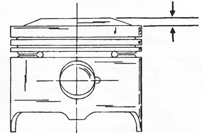
Figure 78. Piston of the old design of the engine with a working volume of 1971 cm³. Pistons of the new design have a larger size, shown by the arrows.
- To check the piston clearance, measure the bore diameter. The holes are measured in the longitudinal and transverse directions and at three levels along the height of the working cylinder liner. In this way the maximum and minimum diameter are determined. Record the results.
- After this, subtract the piston diameter value from the hole diameter values. The difference is the piston clearance value. If the clearance value is outside the range of 0.06 - 0.08 mm, new sets of pistons and cylinder liners should be installed. Install pistons only with the same letter designations. It is quite possible that you will have to scratch off the carbon deposits in order to read the letter.
- Check the piston pins and piston bores for wear and damage. Pins are supplied complete with pistons only. The piston pin must have play in the piston hole, that is, when pressed by the finger, it must move in the piston.
2.5.3. Assembly of pistons and connecting rods
It is assumed that all parts have been checked and repaired in accordance with section 2.5.2.
- Check the absence of twisting and bending of the connecting rods on a connecting rod testing machine. It is best to have this done in a workshop, as bent or even twisted connecting rods can interfere with the normal operation of the engine.
- If the threads are damaged, the connecting rod bearing pin bolts can be replaced separately.
- Lubricate the piston pin and piston pin bore well with engine oil and install the piston on the corresponding connecting rod. The arrow on the piston bottom and the oil injection hole must be positioned as shown in Figure 79.
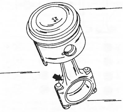
Figure 79. Correct assembly of the piston and connecting rod. Ensure that the arrow on the piston bottom and the oil injection hole are positioned as shown.
- Take the piston and connecting rod assembly as shown in Figure 80 and insert the piston pin. The piston pin is inserted more easily if you preheat the piston in hot water. The retaining ring on the other side of the piston should already be in the groove. Insert the piston until it stops and secure it with the retaining ring. Check the installation of the retaining ring around the entire circumference.
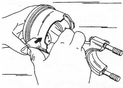
Figure 80. Installing the piston pin.
Note: When reinstalling old parts, they must be installed in accordance with the markings made during disassembly. In any case, the arrow on the bottom of the housing should point towards the front of the engine.
(You can find the original on the page: «peugeotbook.ru»)
- Lubricate the bearing surfaces of the pin with engine oil from an oil can.
- Install the piston rings onto the piston in sequence. The piston ring markings must be located at the top. Before installation, check each piston ring again, as it is easy to make a mistake when installing them. When installing piston rings, you will need piston ring pliers, but you can also place three metal strips around the piston (for example, probes) and put rings on the strips. Pull out the strips when the ring is pushed to the level of its corresponding groove. The rings break easily and must be installed with great care.
- Lubricate the piston rings thoroughly with engine oil and move them around the circumference, correctly positioning the ring joints. Install joint "a" of the oil scraper ring in the place shown in Figure 81, and shift the joints of the other two rings along the circumference of the piston in relation to the joint of the oil scraper ring by 20–50 mm.
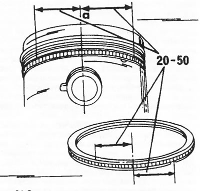
Figure 81. Location of piston ring joints around the piston circumference. The oil scraper ring joint is marked "a." The joints of the other rings are positioned to the left and right of the oil scraper ring joint.
- Lubricate the piston with engine oil and insert it into the corresponding cylinder bore. To compress the piston rings when installing the piston, appropriate compression bands are required. Place the tension band around the piston so that the lower part of the piston jacket remains free. Carefully insert the piston with the connecting rod into the hole (observing the markings), as shown in Figure 82, and then push the piston into the hole from above in the manner shown in the figure.
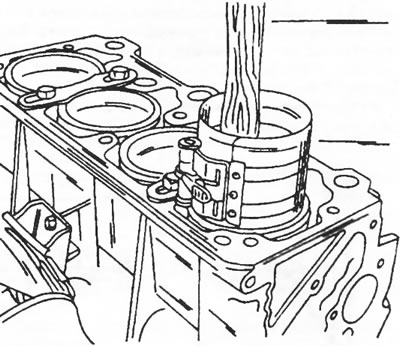
Figure 82. Pistons are inserted into the working liners in the manner shown.
- After installing the working liners, check that the marks on the upper edges of the liners match the marks on the surface of the cylinder block and that all four arrows on the piston crowns point towards the timing drive.
- Install the connecting rod bearing caps. Place the covers in accordance with the cylinder numbers in the required position and tap them firmly. Tighten the nuts alternately to a final tightening torque of 40 Nm.
- Check that the markings on the connecting rods and on the bearing caps on all connecting rods are on the same side.
- After tightening all the connecting rod bearing caps, turn the crankshaft a few revolutions, checking for jamming.