



Table of contents: 2.7.1. Measuring the axial play of…🠇 2.7.2. Checking the details 🠇 2.7.3. Installing the crankshaft 🠇 2.7.4. Replacing the front…🠇 2.7.5. Flywheel 🠇
Removing the crankshaft has already been described in the section on engine disassembly. The crankshaft runs in five bearings. The main bearing journals and connecting rod bearing journals can be turned once, that is, there are bearing shells of the same increased size.
The axial play of the crankshaft is adjusted by means of spacer washers at the rear bearing of the crankshaft.
The crankshaft is sealed at the front by a sealing ring and at the rear by a side sealing strip in the rear main bearing cap of the crankshaft.
What is unusual about these engines is that all the main journal diameters are different, although the thickness of all the main bearing shells is the same.
2.7.1. Measuring the axial play of the crankshaft
Before removing the crankshaft, the amount of its axial play should be determined in order to prepare oversized expansion washers for installation, if necessary. Carry out the following work:
- Install a dial indicator on the front side of the cylinder block, as shown in Figure 42, and press the crankshaft along the axis in one direction with a screwdriver. Reset the dial indicator scale to zero.
- Press on the crankshaft with a screwdriver from the other side and read the reading from the dial indicator scale. The value must be within the tolerance range. Record the measurement result. If it exceeds the wear limit, oversized spacer washers must be installed during assembly (sometimes only the expansion washers wear out).
- Remove the dial indicator.
- Remove the crankshaft in accordance with the instructions in section 2.2.
2.7.2. Checking the details
- Clean the crankshaft thoroughly. Pay special attention to the cleanliness of the lubrication holes.
- Carefully check the crankshaft for damage and take precise measurements of the main and connecting rod journals with a micrometer. In this case, proceed in accordance with Figure 83. The right side of the figure shows the directions of measurements for each neck, that is, six measurements must be taken on each neck. The difference between the measurement in the direction towards the crankshaft web and the measurement in the direction perpendicular to the crankshaft web determines its out-of-roundness; the difference between the measurement at one end and the other end of the crankshaft determines its taper. Both differences should not exceed 0.007 mm. The crankshaft main bearing cheeks and crankpin journals may be ground once to allow the crankshaft to be installed with oversized bearing shells.
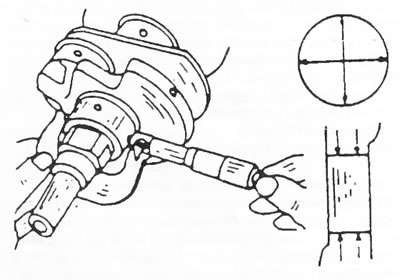
Figure 83. Measuring the crankshaft main journals. The directions of measurements are shown on the right side of the figure.
- Clamp the crankshaft in the centers of a lathe or place the outer journals of the shaft in prisms, as shown in Figure 84, and check the shaft runout by installing the measuring probe of the dial indicator on the middle journal. The runout should not exceed 0.02 mm. Otherwise, the crankshaft must be replaced.
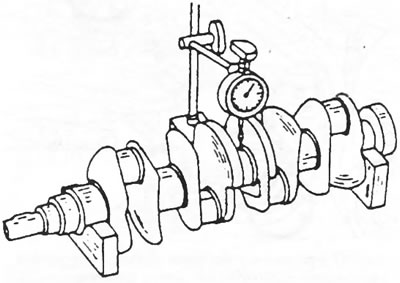
Figure 84. Measuring crankshaft runout.
(Article based on material from the website: PEUGEOTBOOK)
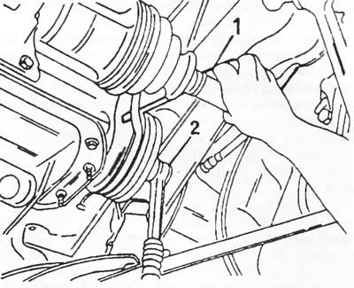
Figure 85. Insert a screwdriver (1) under the drive belt and turn the crankshaft with a ratchet wrench head (2) until the belt slips.
2.7.3. Installing the crankshaft
The crankshaft installation procedure is described in conjunction with engine installation in Section 2.3. It is imperative that the bearings, which have lubrication grooves, be installed correctly, as indicated in the above section. It is necessary to install both expansion washers of the same thickness.
2.7.4. Replacing the front crankshaft oil seal (as well as the timing chain drive covers)
The front oil seal is located behind the crankshaft sprocket in the timing chain cover and can be replaced without removing the engine. To remove the oil seal, you can try to screw two self-tapping screws into the oil seal and then pull the oil seal out with a screwdriver.
The engine must be supported from below, as the engine mount on the timing drive side must be removed.
In general, when replacing the oil seal or when removing and installing the timing chain cover, the following work is performed:
- Disconnect the wires from the battery. Move the wires away from the battery so that they do not touch the battery terminals and cause a short circuit.
- Remove the alternator drive belt.
- After this, place the front of the vehicle on stands to provide access to the water pump drive belt. Remove the belt by inserting a screwdriver between the belt and the belt pulley as shown in Figure 22 and turning the crankshaft belt pulley with a 35 mm wrench until the belt comes off. Be careful not to damage the belt.
- Loosen the crankshaft belt pulley nut. At the same time, you should hold the crankshaft from turning. To do this, either unscrew the cover under the flywheel housing and lock the flywheel by inserting a screwdriver into the teeth of the flywheel ring gear, or engage the gear. A 35mm wrench head is required to loosen the nut.
- After this, support the engine from below (place a jack with a wooden shim under the oil pan) or lift the engine with a hand crane on a suitable cable.
- Remove the engine mount shown in Figure 71. To do this, unscrew the three water pump mounting bolts, unscrew the nut (1) in the middle of the engine mount, and remove the aluminum support bracket (2). Before removing, be sure to check that the engine mount is secure.
- Remove the belt pulley. If necessary, use two pry bars to press the pulley.
- Remove the timing cover and replace the seal in the usual way or remove the seal from the cover in the above manner. If it is necessary to remove the cover, use side cutters to pull the key out of the crankshaft.
Note: Do not remove the ignition timing adjustment bar from the cover or loosen the screws that secure it.
- Lubricate the sealing lips of the new oil seal with engine oil and press the oil seal into the cover. If the lid is unscrewed, screw it back on (with a new seal installed), slightly tightening the bolts to center the cover on the crankshaft. The seal should either be carefully hammered in or driven in using a piece of pipe of the appropriate diameter and a large washer. The crankshaft belt pulley nut can also be used for this purpose. After this, tighten the cover mounting bolts.
- When installing the seal, care must be taken not to damage the sealing lips of the seal.
- Drive the key into the crankshaft.
- Place the crankshaft belt pulley on the crankshaft and then place the belt loosely on the back of the pulley.
- Raise or lower the engine so that the engine support can be screwed on. Tighten the three water pump bolts to 55 Nm and the center nut to 55 Nm.
- Remove the engine lifting device.
- While holding the crankshaft from turning, tighten the belt pulley nut to a torque of 170 Nm.
- Just as when removing, insert the water pump belt into the groove of the crankshaft pulley.
- Install the alternator belt and adjust its tension.
2.7.5. Flywheel
If the flywheel ring gear is damaged, it is also necessary to check the starter pinion, as both parts wear out together.
The flywheel bolts are staggered so that the flywheel can only be installed in one position. When installing the flywheel, coat the bolt threads with Loctite. Tighten the bolts evenly and crosswise to a torque of 67.5 Nm.