



Table of contents: 2.4.1. Removal 🠇 2.4.2. Disassembly and repair 🠇 2.4.3. Cylinder head assembly 🠇 2.4.4. Installing the cylinder head 🠇 2.4.5. Adjusting valve clearances 🠇
2.4.1. Removal
The cylinder head can be removed without removing the engine. This work has already been described in section 2.2.1.
2.4.2. Disassembly and repair
After removing the cylinder head, all its parts can be removed. Therefore, the following text is limited to a description of valve removal only.
Valves
- If this has not been done previously, remove the distributor and remove the spark plugs.
A special tool is required to remove the valves from the cylinder head. It is shown in Figure 60, but does not necessarily have the shape shown.
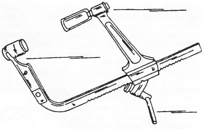
Figure 60. Valve spring compressor
If you don't have a special tool, the valves can also be removed in the following way:
* Place a block of wood into the combustion chamber so that it rests against the valve to be removed.
* Place a piece of tubing of the same diameter as the valve spring cup against the top of the valve spring cup and strike the tubing sharply with a hammer. At the same time, the valve spring is compressed and both crackers are released.
* Remove the valve parts and pull out the valve from the other side of the cylinder head. Immediately mark the installation position of the valves accordingly and fold the removed valves in the appropriate order.
Minor damage to the valve surfaces can be repaired by lapping the valves in the cylinder head seats as described below. Measure the valves to ensure they comply with the size and adjustment table and replace any valves that are out of tolerance.
- If the ends of the valve stems are worn, they can be processed on a grinding machine, provided that the correction requires removing no more than 0.50 mm of material.
- The valve heads are processed on a special machine for grinding valves, provided that the thickness of the valve head, shown by the arrows in Figure 61, after processing will be at least 0.5 mm.
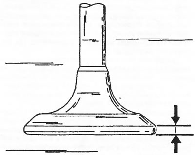
Figure 61. The thickness of the valve head between the arrows must not be less than a certain value.
- Check the valve stems and, in connection with this, the inside diameter of the valve guides, which requires a standard micrometer and an inside diameter micrometer. To do this, measure the valve stems in various places using the method shown in Figure 62. After this, measure the corresponding valve bushing as shown in Figure 63. If there is wear, i.e. the difference in dimensions is more than 0.1 mm, the guide bushings should be replaced (see the section "Guide bushings").
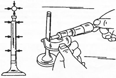
Figure 62. Measuring the valve stem diameter. The measurement locations are shown on the left.
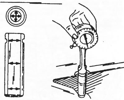
Figure 63. Measuring the inner diameter of the valve guide. The measurement locations are shown on the left.
Valve seats
Check all valve seats for signs of wear and build-up. Minor wear can be eliminated with a 45° cutter (intake valves) or 60° (exhaust valves). If there is significant wear, the valve seats must be re-milled or the valve seat rings must be replaced. The final work involves drilling out the receiving holes for the seats and must be done in a special workshop. When milling, take into account that the inlet and outlet valves have different angles (inlet valves 120°, outlet valves 90°).
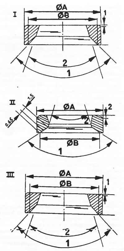
Figure 64. Valve seat dimensions. The top figure (I) shows the intake valve seat of the XM7-T engine. The middle figure (II) shows the intake valve seat of the XN1-T engine. The bottom figure (III) shows the intake valve seats. Valve seat dimensions have changed during production and are contained in the table of dimensions and adjustments. A = receiving hole in the cylinder head; B = valve seat diameter; 1 = valve seat angle 2 = correction angle
When installing new valve guides, milling of the valve seats is required. An angle cutter is used for this (Figure 65), which is also different for the intake and exhaust valves:
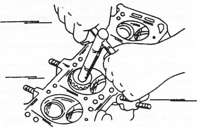
Figure 65. Milling the valve seat
- Mill the valve seat corner and then lightly finish the top edge of the valve seat with a corner milling cutter to reduce the valve seat width to approximately 1.5 mm. Milling should be stopped once the seat width is less than the specified value.
- Lapping the machined valve seats. To do this, apply a little grinding paste to the surface of the seat and insert the valve into the corresponding seat. Place a suction cup on the valve and turn the valve as shown in Figure 66.
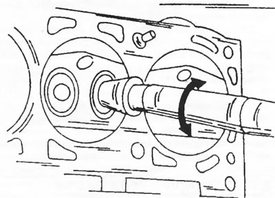
Figure 66. Valve grinding.
- After lapping, clean all parts from dirt and grinding paste and check the valve head seat and seat ring. Both parts should show a continuous matte ring that defines the valve seat width.
- Apply a few strokes with a pencil to the ring on the valve head. The strokes should be applied at a distance of approximately 1 mm around the circumference. After this, carefully insert the valve into the guide sleeve and turn the valve 90°, while lightly pressing on the valve.
- Remove the valve and check if the ring marks on the valve head ring have disappeared. If the valve seat width is within the specified limits, installation can be performed. Otherwise, the valve seats will need to be machined or, in the worst case, the cylinder head will need to be replaced. In this case, all parts are removed from the old cylinder head and transferred to the new one.
Valve springs
To reliably test valve springs, a certified spring testing device is required to measure the spring length under load. If such a device is not available:
- Compare the removed spring with the new one. For this purpose. press both springs in a vice and slowly close the vice. If both springs compress approximately the same amount, then this is a sure sign that they have approximately the same spring force. If the old spring compresses significantly more than the new one, this is a sign of fatigue and all springs must be replaced as a set.
- Place the springs on a flat surface (on the glass) so that the closed one is located at the bottom. Place a steel square next to the spring. Measure the gap between the spring and the square at the top; it should not exceed 2.0 mm. Otherwise, the spring is warped.
- Measure the length of the unloaded springs in accordance with Figure 67. Although there is no exact data, it can be considered that the springs are suitable for installation if they all have the same length.
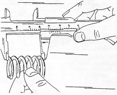
Figure 67. Measuring the length of the valve spring in a free state.
- Each valve is equipped with two springs of different lengths. The inner springs are wound on the left, and the outer springs on the right. It does not matter which side the spring is installed on the cylinder head.
Valve guide bushings
To accurately measure valve guides and valve stems, a micrometer is required, the use of which is shown in Figures 62 and 63. If the difference between two measurements exceeds 0.10 mm, the corresponding guide (or all of them) should be replaced. If a micrometer is not available (micrometer for measuring the internal diameters of valve guides), valve stem clearances can be determined as follows:
- Clean the valve guides by drawing a clean cloth soaked in gasoline through them. Also thoroughly clean the valve stems and then sequentially insert the valves into their corresponding holes.
- Place a dial indicator on a stand on the top side of the cylinder head and press the valve out of the hole until the end of the valve stem fits under the face of the guide sleeve on the other side of the cylinder head.
- Shake the valve head from the top in different directions and read the readings from the dial indicator scale. If the scale reading exceeds 1.0 - 1.2 mm, the guide bushing most often needs to be replaced.
- Before replacing the guide bushing, check the general condition of the cylinder head. Cylinder heads that have small cracks between the valve seats can continue to be used and ground, provided the cracks are not very large.
- To replace the guide bushing, press out the old guide bushing using a suitable rod. In order to be able to knock out the valve guide, the cylinder head must be heated in hot water. Before pressing out the guide bushing, measure the size of the bushing protrusion from the top side of the cylinder head. The rod used for pressing out the guide bushings must have its neck machined to the inner diameter of the guide bushing.
- When replacing the guide bushings, it is necessary to replace the valves at the same time. This requires treatment of the valve seats. There are oversized guide bushings and the receiving holes in the cylinders must be reamed accordingly.
- Lubricate the new guide bushings thoroughly with engine oil and press them into the cylinder head so that the dimension "X" in Figure 68 has the specified value for the intake and exhaust valves. The figure also shows the inclined position of the guide bushings, that is, to press in the bushings, it is necessary to tilt the cylinder head, placing a lining under it on one side.
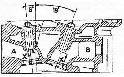
Figure 68. Sectional view of the cylinder head showing the location of the exhaust valve guides (A) and intake valve guides (B). Dimension "X" determines the installation height of the guides. Exhaust valve guide dimension "X" = 21.3 mm; Dimension "X" of intake valve guides = 31.5 mm
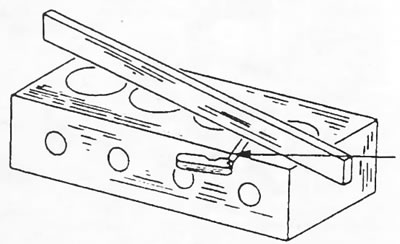
Figure 69. Checking the cylinder head surface distortion. Insert the feeler gauge into the place indicated by the arrow.
- After pressing, adjust the diameter to 8.02 mm + 0.022 mm. This will achieve the required valve stem clearance.
- When replacing the guide bushing, it is necessary to mill the valve seat. All guide bushings and valves are replaced at once.
Cylinder head
Thoroughly clean the mating surfaces of the head and cylinder block and check that the cylinder head is not warped. To do this, place a measuring ruler on the cylinder head and use feeler gauges to measure the gap between the ruler and the surface of the head along, across and diagonally. If a feeler gauge thickness greater than 0.10 mm can be inserted, the cylinder head must be milled. If there are significant gaps, the cylinder head must be replaced.
Cylinder head milling is possible as long as the head height after machining is at least 92.10 mm.
Camshaft
The camshaft is the same on all engines. The camshaft is secured to the cylinder block by a retaining plate. The plate fits into a groove on the camshaft and thus prevents it from shifting.
To remove the camshaft, use pliers to pull out the spring washer and unscrew the retaining plate. Pull out the camshaft carefully, without hitting the bearing bushings with the cams or journals of the shaft.
Mount the camshaft with its end journals on the prisms, as shown in Figure 70, or clamp the shaft in the centers of a lathe and attach a dial indicator to the middle journal of the shaft. Slowly turn the camshaft and read the readings on the dial indicator scale. If the measurement result exceeds 0.01 mm, the shaft is bent and requires replacement.
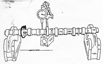
Figure 70. Checking camshaft runout.
Check the shaft journals for visible damage. If any are found, further work may not be necessary.
To measure the axial clearance of the camshaft, place it in the cylinder block and secure it with a retaining plate. Place a dial indicator on the end of the shaft and move the camshaft in both directions in the axial direction. If the clearance exceeds 0.14 mm, the retaining plate is worn and should be replaced. In the worst case, the camshaft flange may be worn out. This means that it is necessary to carefully examine all the parts so as not to replace the camshaft in vain.
2.4.3. Cylinder head assembly
When replacing a cylinder head, the ignition distributor, exhaust manifold, spark plugs, temperature switch, etc. are transferred from the old cylinder head to the new one. Clean all parts thoroughly and lubricate all moving parts well with engine oil.
- Insert the valves into their guide bushings. If the valve seats have been machined, they must be installed in the corresponding bushings. The same applies to used valves, which must be installed in their original locations.
- Install new valve stem seals on each guide bushing.
- Insert valves (well lubricated with motor oil) into the cylinder head from the bottom side and place both springs on top of each valve. Compress the springs with a special spring compressor. With the end of the valve stem protruding from the top side, use tweezers to insert the valve crackers. Slowly release the spring compressor and check that the valve springs are seated properly in the valves.
- Hit the top of the valve stems with a plastic hammer. At the same time, poorly seated crackers pop out. For safety, place a rag on the ends of the springs to prevent the parts from flying apart.
- Further assembly is carried out in reverse order.
2.4.4. Installing the cylinder head
Installation of the cylinder head is described in detail in section 2.3, dedicated to engine assembly, and there is no need to repeat the description. All removed parts are installed in reverse order. When installing a cylinder head on an engine mounted on a vehicle, the following points must be taken into account:
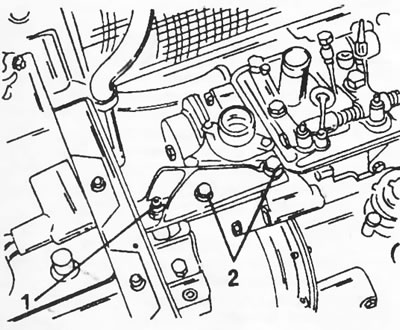
Figure 71. Engine mount from the front of the engine. 1. Nut, 55 nm; 2. Bolts, 50 nm
- Tighten the engine rubber mount nut to 55 Nm (Figure 71).
- Tighten the three water pump bolts to 50 Nm (Figure 71).
- Tighten the connection of the pipe to the exhaust manifold until the distance between the arrows in Figure 18 "X" is 22.0 mm.
- Tighten the alternator drive belt as described in in the relevant section.
- Pour 9 liters of coolant into the cooling system.
- Don't forget that on certain engines, after a certain mileage, it is necessary to tighten the cylinder head bolts. More detailed information on this matter was given above.
2.4.5. Adjusting valve clearances
If valve clearance adjustments are being made with the engine installed in the vehicle, which is most often the case during general valve clearance checks, preliminary work must be performed to provide access to the valves. To do this, it is necessary to remove the cylinder head cover and carry out all associated work, such as removing the air filter, disconnecting certain hoses, etc. Checking and adjusting valve clearances can be done in two ways, which are described below.
- Turn the engine until the exhaust valve of the first cylinder is fully open. In this position, adjust the intake valve of the third cylinder and the exhaust valve of the fourth cylinder. To easily turn the engine, lift the front wheel, engage one of the high gears and turn the wheel until the engine is in the desired position. The second wheel must be on the ground. To relieve compression, you can screw in the spark plugs.
- Crank the engine until the next exhaust valve opens. The valve adjustment is carried out in accordance with the table below and using Figure 72, which also shows the positions of the camshaft cams. The valves with crosses are exhaust valves, and the valves marked with a black circle are intake valves. The valves that need to be adjusted are shown on the right:
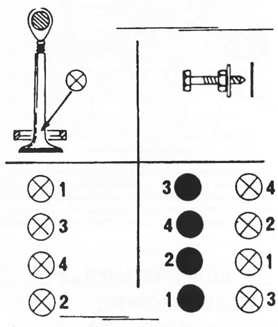
Figure 72. Adjusting valve clearances.
The intake valves are marked with circles with a cross, and the exhaust valves are marked with black circles. When opening the corresponding inlet valve, adjust the valves indicated on the right side.
- Adjusting the valve clearances can also be done in another way, when the engine is turned until both valves of the first cylinder are completely closed. This position can be controlled by the fourth cylinder, the valves of which must intersect. When turning the engine from this position in both directions, it is visible that one valve of the fourth cylinder rises and the other valve falls. In this position, the rocker arms have clearances and both camshaft lobes are in the position shown in Figure 73. After adjusting the valve clearances of the first cylinder, the engine is turned another half turn and the next pair of closed valves is adjusted. The following table shows the valve clearance adjustment diagram:
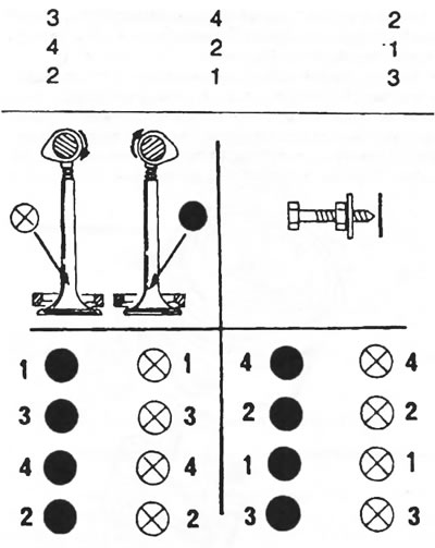
Figure 73. Adjusting valve clearances when the valves of the cylinders indicated on the left are closed. The valve clearances of the cylinders indicated on the right are adjusted.
- To check the valve clearance, insert a feeler gauge of the required thickness between the end of the valve stem and the rocker arm, as shown in Figure 74. To adjust the clearances of the intake valves, a feeler gauge of 0.10 mm thickness is required; to adjust the exhaust valve clearances, you need a 0.20 mm feeler gauge. The clearance tolerance for all valves is ±0.05 mm. The feeler gauge should fit easily, but not too loosely, into the gap. A sign of good adjustment is when the feeler gauge enters without jamming, bends slightly, and then jumps into the gap between the valve stem and the rocker arm.
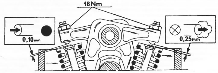
Figure 74. Insert the feeler gauge into the gap indicated by the arrows between the end of the valve stem and the adjusting screw. Tightening torque of the lock nut is 18 Nm.
- When adjusting the valve clearance, use a socket wrench to loosen the lock nut and a screwdriver to turn the adjusting screw. When tightening the lock nut, hold the adjusting screw to prevent it from coming loose. Tighten the nuts to a torque of 18 Nm.
- Finally, check the clearances of all valves once again.