



- Before assembly, it is necessary to check that all parts are clean and do not contain foreign objects. This should be done just before assembly, and not when the parts are already assembled, since otherwise the oil access to the immediate support points may be blocked. It is especially important to ensure that the pistons, piston rings and cylinder walls are thoroughly lubricated before assembly.
- Thoroughly clean all cylinder block parts if the engine has been completely disassembled. When partially disassembling the engine, do not allow foreign objects to enter the disassembled parts or cavities of the engine. To avoid this, all holes should be either sealed or covered with rags.
- It is best to blow out lubrication channels and holes with compressed air. If compressed air is not available, clean all channels and holes with a wooden stick, but under no circumstances with metal objects. When assembling, be sure to install new seals, gaskets, etc. Under no circumstances should you skimp on these parts or install obviously damaged ones.
- The table of sizes and adjustments shows the wear limits of the main moving parts. If in doubt or if the wear limit is approaching, it is better to replace the part, thereby saving on disassembling the engine in the near future.
- All spare parts should be purchased only from Peugeot/Fiat/Citroen dealerships, indicating the engine number. Since modernization and, consequently, changes in parts are constantly taking place, only your supplier can provide the necessary spare part.
- Before direct assembly of the engine, it is necessary to measure the dimensions of the protrusions of the working cylinder liners. At the base of the working sleeves there are seals that determine the size of the sleeve protrusion. In almost all cases, the dimensions of the protrusions comply with the standard, but for reliability they should be controlled. In this case, it is necessary to take into account the existing modifications carried out since the beginning of engine production.
The size of the protrusions of the cylinder liners is checked as follows:
- Insert working liners without sealing rings into the cylinders. In this case, the marks on the sleeves and on the cylinder block must be located in the same line and the surfaces of the sleeves must fit correctly in the cylinder holes. Press the cylinder liners firmly.
- Measure the protrusion size of each working sleeve using a depth gauge or the measuring block shown in Figures 34 and 35. In this case, measure the size of the protrusion of each sleeve in places from A to D and record the maximum measurement result. The difference in measurement results should not exceed 0.07 mm. Otherwise, a foreign object may have burst between the liner and the cylinder block seat. Remove the sleeve and check.
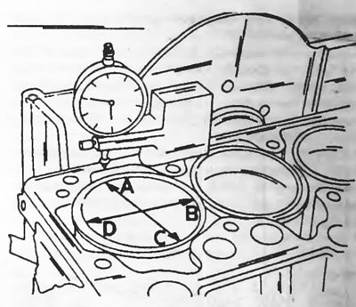
Figure 34. Place the measuring block as shown. Sequentially install the measuring probe in places A to D and record the maximum dimension.
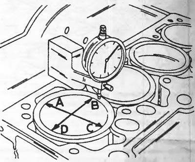
Figure 35. After the measuring unit is installed as shown in Figure 34 (with zeroing of the instrument scale), take measurements at locations A to D.
- Cylinder liners on engines produced before April 1989 should have dimensions between 0.07 and 0.14 mm after installation of sealing rings. Aim to always keep the protrusion as close to 0.14 mm as possible. On later-produced engines, the protrusion should be between 0.03 and 0.10 mm. Here, too, the maximum dimension should be strived for.
- Depending on the year of production, sealing rings are made from different materials. Until July 1985, they consisted of paper and white, synthetic fibre material. Since July 1985, steel sealing washers in aluminum castings have been used. All seals are marked on the outside with "tick marks", however the markings on old and new seals are also different. The table below provides a breakdown of the markings for the engines described.
- Paper seals produced before July 1985. Steel seals produced after July 1985.
- Only one ring is installed under each sleeve. The working liners are measured on both sides of the cylinder block.
- If the protrusion size is not normal, the corresponding cylinder liner should be pulled out again and the cause of the deviation should be determined or dirt should be found, as a foreign object may have gotten between the cylinder liner and the seat in the cylinder block.
- After this, pull out the working sleeve again and place the sealing ring in the place shown in Figure 36. In this case, certain precautions must be taken. The sealing ring has a protrusion (1) that fits into the guide groove in the working sleeve. The second protrusion (2) serves to mark the seal and must be located parallel to the surface (3) on the sleeve. When removing all working cartridges, they must be marked accordingly.
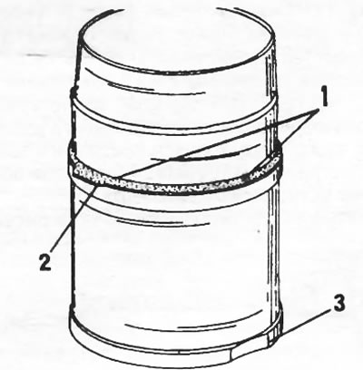
Figure 36. Cylinder working sleeve with installed sealing ring. The decoding of the numbers is given in the text.
- After this, the engine can be assembled in the following order. The condition is inspection and, if necessary, replacement of defective parts.
- Screw the plugs into the crankshaft. Since the previous plug was tightened, it may happen that the threads are damaged. In this case, use an M25x1.5 tap to a depth of 10 mm. Always install new plugs and tighten them to a torque of 55 Nm. After tightening, secure the plug by pressing the thread with a sharp punch from the inside of the crankshaft to prevent the plug from loosening. As can be seen from Figure 37, the plug is screwed in quite deeply, that is, for locking, the core should be placed as shown in the figure. It is imperative to take safety precautions.
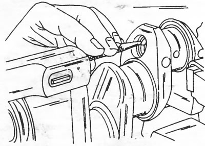
Figure 37. Locking the lubrication channel plug in the shaft. Not all crankshafts have these plugs.
Note: Crankshafts are also available without oil channel plugs. When installing such shafts, the location of the main bearing shells also changes (see below in the text).
- According to the markings, tighten the counterweights to the crankshaft with a tightening torque of 67.5 Nm. A counterweight is installed under the bolts; after tightening, the counterweight should bend. This work should also be done very carefully. Tighten the bolts so that one of the edges of the heads is located on the outside. After this, hit the drift with a hammer, pressing the locking piece against the bolt head, as shown in Figure 38.
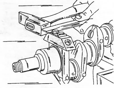
Figure 38. Locking the crankshaft counterweight mounting bolts.
- If removed, install a new clutch shaft bushing (outward bevel). Press in a new oil seal and lightly lubricate the oil seal and bushing with engine oil.
After this, the main bearing shells are inserted into the cylinder block, depending on the design of the crankshaft. To avoid mistakes when performing this work, please refer to Figure 39:
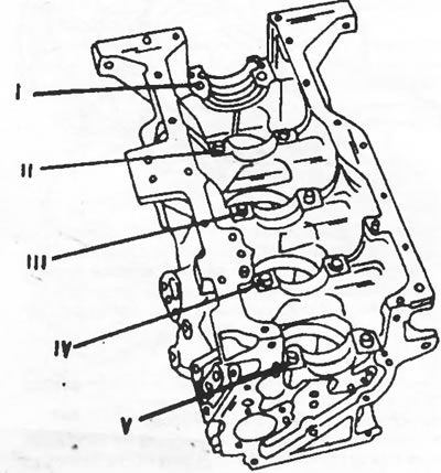
Figure 39. Location of crankshaft main bearings.
Crankshafts with plugs
- Insert liners with lubrication grooves into bearings I, III and V.
- Insert liners without lubrication grooves into bearings II and IV.
Crankshafts without plugs
- The liners with lubrication grooves are installed in the cylinder block.
- Liners without lubrication grooves are installed in main bearing caps.
- Lubricate the inserted main bearing shells thoroughly with engine oil and carefully insert the crankshaft into the bearing holes.
- Turn the crankshaft several times to settle the bearings.
- Insert two spacer washers from the flywheel side to remove the axial play of the crankshaft. The oil grooves must face towards the crankshaft.
- Place the main bearing caps with liners on the cylinder block in accordance with the markings made during removal (well lubricated). Lubricate the bearing shells thoroughly.
- Install the rear main bearing cap without side seals, but with an axial play compensation half-washer (Figure 40). In this case, the oil grooves must also face the crankshaft.
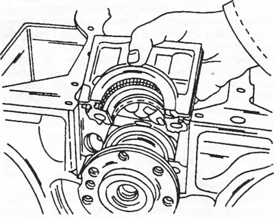
Figure 40. Install the rear main bearing cap with the half washer, but without the side seals.
- Sequentially, going from the inside to the outside, tighten the cover bolts in several passes to a final tightening torque of 75 Nm.
- After this, check the axial play of the crankshaft as follows:
* Mount the dial indicator on the appropriate gauge on the front side of the engine and place the measuring rod of the instrument on the surface of the crankshaft counterweight as shown in Figure 41.
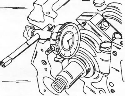
Figure 41. Measuring the axial play of the crankshaft. Place the measuring rod of the device on the surface of the crankshaft counterweight.
* Press the crankshaft with a screwdriver on one side and set the indicator scale to zero.
* Press on the crankshaft from the other side and read the reading from the dial indicator scale. The measurement result should be between 0.08 and 0.20 mm.
* If the measurement result exceeds 0.20 mm, two larger half washers must be installed. Both washers must be the same thickness. Washers with a thickness of 2.30 are available; 2,35; 2,40; 2.45 and 2.50 mm. To prevent crankshaft misalignment, it's important to install washers of the same thickness. If the axial play is less than 0.08 mm, then there is an error somewhere during crankshaft installation, which must be identified and corrected.
- After this, it is necessary to install the rear main bearing cap and side seals as follows. At the service station, a special tool is used to insert the seals into the guides.
- Press the new rubber seals into the cover and place the device shown in Figure 42 against the cover so that its bars press the rubber seals. Lubricate the guide strips located on the sides with engine oil and place them all together in the cylinder block above the crankshaft. After installing the cover and seals, the device is removed. If there is no special device (in most cases this is exactly the case), insert thin steel strips between the rubber seals and the cylinder block and install the cover in this manner. Tap the lid lightly until it seats properly and then remove the steel strips.
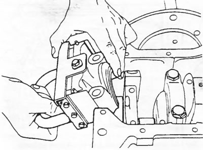
Figure 42. Installing the rear bearing cover together with the tool for pressing in the side rubber seals. The side bars should be inserted from the left and right.
- Tighten the cover bolts to a tightening torque of 75 Nm.
- The protruding ends of the seals should be trimmed, but a 2.0 mm protrusion should be left. To do this, take a piece of sheet metal of this thickness and drill a hole in it the same diameter as the seals. Place this piece of sheet metal as shown in Figure 43 and trim the seal evenly. The thickness of the sheet metal must be 2.0 mm.
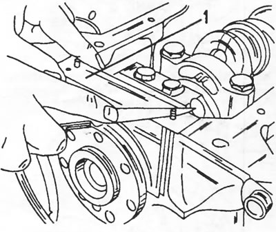
Figure 43. The protruding ends of the seals must be cut off. Place a piece of tin (1) in the manner shown.
- Thoroughly clean the mating surfaces on the crankshaft and flywheel, as well as on the flywheel itself, and coat the bolt threads with Loctite. Install the flywheel and tighten the bolts evenly around the circumference to 67.5 Nm. To prevent the crankshaft from turning, insert a wooden wedge into the crankcase against the main journal.
- Insert the driven clutch disc into the flywheel and insert the centering rod into the disc and into the guide bearing (see also section "Clutch installation"). Install the clutch basket (when installing the removed parts, observe the markings made during removal and tighten the bolts evenly around the circumference to a torque of 15 Nm. At the same time, pull out and reinsert the centering rod to ensure the disk is centered.
- Insert the working cylinder liners into the cylinder bores together with the sealing rings or steel washers. The marking protrusions must be offset, that is, they must be located on the first cylinder on one side, and on the next cylinder on the opposite side.
- It is necessary to ensure the required size of the protrusion of the working sleeves with inserted seals. This means pressing the working liners into the cylinder bores. At the service station, a special device is used for this purpose, which creates the necessary pressure, which is shown in Figure 44. This work can be performed in the same way when installing the block under a bench drilling machine. It's important to note that the liner protrusion on engines produced before April 1989 should not exceed 0.14 mm, while on engines produced later, it should not exceed 0.10 mm. In addition, the difference in protrusion between two adjacent cylinder liners must be measured. The measurement is carried out in the same way as shown in Figure 35, with the difference that the measuring probe of the device is installed each time on the edge of two adjacent working sleeves. If the difference in protrusions is more than 0.04 mm, it is necessary to replace the seal of the sleeve with the larger protrusion.
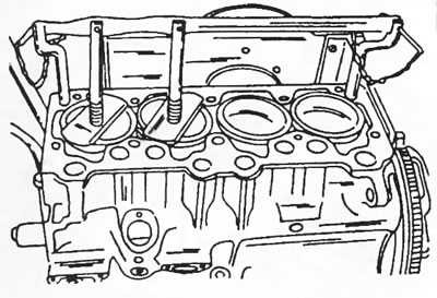
Figure 44. Device for pressing working sleeves. Before taking an accurate protrusion measurement, the sleeve must be pressed.
- After taking measurements, install clamping strips on all working sleeves to prevent the working sleeves from falling out.
- Assemble the pistons and connecting rods as described in section 2.5.3.
- Install the pistons into the cylinder liners as described in the relevant section.
- Insert the connecting rod bearing shells into the connecting rods in accordance with their markings (if the same liners are reinstalled). The guide tabs of the bearing shells must fit into the grooves of the connecting rod holes. Installation of pistons/connecting rods, piston rings, etc. is described in the section "Pistons and connecting rods".
- Lubricate the bearing journals with engine oil and insert the camshaft into the cylinder block. The shaft is secured with a retaining plate. Insert the board into the groove on the camshaft and then screw it to the cylinder block. Tighten the fasteners to a torque of 10 Nm.
- Place the chain sprocket onto the crankshaft from the front side. The key should fit into the groove, and the ignition timing mark should be located on the outside.
- Turn the crankshaft and camshaft so that the marks on both sprockets are located opposite each other. This is a very important work operation. After the stars have been placed, their relative positions should be compared with Figure 45.
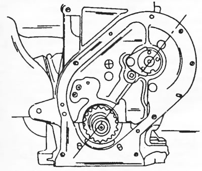
Figure 45. Turn the crankshaft and camshaft so that the marks on both sprockets are located opposite each other.
- Place the chain on the crankshaft sprocket and insert the sprocket into the chain from the other side. Check that the marks are positioned as shown in Figure 46 and secure the sprocket to the camshaft. If the marks on the chain are not visible, the chain should be applied in accordance with the markings made during removal.
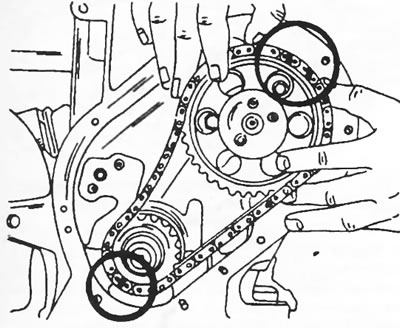
Figure 46. When applying the chain, observe the location of the marks.
- Place a new locking plate on the camshaft sprocket, install the three bolts, and tighten the bolts to 23 Nm. Tap the locking plate around the bolt heads.
- Disassembling and assembling the chain tensioner. As already mentioned, two types of tensioning devices can be installed. The following description assumes that the tensioner is disassembled. Before installing the old tensioner, it should be disassembled to check that the clamp can move freely and that the grease holes are not clogged. To ensure normal operation of the tensioner, it must be pre-tensioned.
Sedis chain tensioner
The Sedis chain tensioner is shown in Figure 47. During disassembly, the following operations are performed:
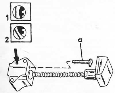
Figure 47. Sedis chain tensioner. Details are given in the text.
- Set the ratchet mechanism in the position not indicated in the square (1) and pull out the clamp together with the spring. Do not remove the ratchet bar (a) from the hole, as it will then be impossible to reinstall it.
- After cleaning all parts, assembly is carried out in reverse order. Lock the tensioner by setting the ratchet mechanism to the position shown in square (2).
Renold chain tensioner
- Insert a 3mm Allen key into the Allen key as shown in Figure 48 and turn the key until the tensioner locks.
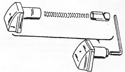
Figure 48. Towards the assembly of the Renold tensioner.
- Insert the clamp into the tensioner housing.
- The new tensioner is supplied with a locking washer that is inserted between the tensioner body and the inside of the clamp and is only removed after the tensioner is installed. When installing the existing tensioner, insert a piece of 2 mm diameter steel wire in the location shown in Figure 49. This prevents the tensioner from shifting.
- After this, the tensioner is pre-tensioned as follows:
Sedis chain tensioner
Insert a screwdriver into the hole shown in Figure 29 and turn the ratchet mechanism to the right, (and not to the left, as shown in the picture).
Renold chain tensioner
Remove the locking washer (1) or piece of wire (2) shown in Figure 49 and press the chain from the inside out to move the clamp in the tensioner. After releasing the chain, the tensioner is ready for operation.
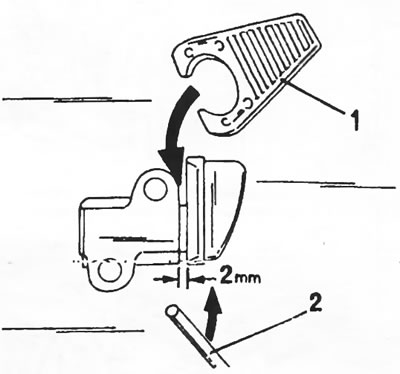
Figure 49. The Renold chain tensioner is supplied with a locking washer (1). When reinstalling the old tensioner, a piece of steel wire (2) is inserted in this position. The tensioner must only be installed in this position.
Note: On both designs, pre-tensioning by moving the clamp is prohibited.
- Screw on the timing cover with a new gasket. In this case, the cover must be precisely centered, which is necessary for installing the seal. A piece of tubing can be used to install the seal lubricated with engine oil. Place the seal on the cover, install the tube and screw the large belt pulley nut onto the shaft. The seal is pressed in by pressing the tube onto it. Tighten the cover bolts to 13 Nm.
- Drive the key into the crankshaft and place the belt pulley on the key and shaft. Block the crankshaft from turning with a wooden wedge and tighten the nut to a torque of 170 Nm.
If the ignition timing indicator plate was removed, it should be installed to determine the top dead center:
- Turn the engine until the pistons of the first and fourth cylinders reach the exact position of top dead center, while the valves of the fourth cylinder should be in the switching phase, that is, one of the valves should open and the other should close. The exact position of the top dead center is determined using a dial indicator, which is positioned as shown in Figure 50.
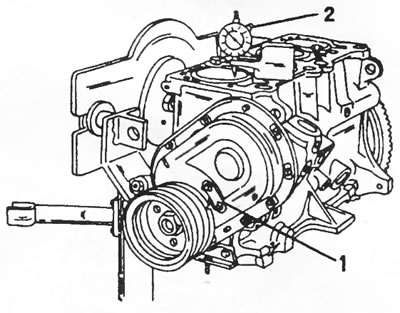
Figure 50. To correctly install the plate with the ignition timing indicator (1), determine the position of the top dead center of the specified piston using the dial indicator (2). Only then tighten the plate.
- Screw on the plate with the indicator for setting the ignition timing so that the "zero" on the plate is located opposite the mark on the crankshaft belt pulley. Tighten both plate mounting nuts. Mark one of the nuts with paint (for subsequent purposes).
- Install the oil pump and distributor drive shaft. In this case, the piston of the first cylinder should be at the top dead center of the ignition moment. Insert the shaft so that the spline in the drive gear is horizontal to the centerline of the engine. The leash slot is offset from the center. After installation, the smaller segment should face the engine. After this, push the shaft inward until it stops. In this case, the shaft engages with the helical gear of the camshaft and turns. In this case, the drive spline should move from the bottom left to the top right, and the smaller segment should face the rear side of the engine.
- Install and tighten the ignition distributor clamp.
- Install the oil pump. First, check that the adapter sleeve is inserted into the cylinder block. Put on a new O-ring and install the oil pump. At the same time, turn the shaft to ensure engagement. Tighten the bolts to a torque of 10 Nm.
- Install the oil pan with a new gasket. Tighten the bolts to a torque of 10 Nm.
- Lubricate the valve lifters well with engine oil and insert them into the holes. Install new tappets into the old holes.
- Remove the cylinder liner clamping bars. At the same time, check once again that the surfaces of the flanges of sleeves 1 and 2, as well as 3 and 4, are located parallel and across the engine.
After this, the cylinder head is installed. Since the tightening method for cylinder head bolts has changed three times during engine production, it is essential to adhere to the year of engine production. You should also install a cylinder head gasket that matches the engine of a specific year of manufacture:
- Screw two guide pins into both corner holes on the side opposite the distributor. Since the special pins used at the service station are usually not available, they can be made from bolts of the same diameter. To do this, you need to cut off the head of the bolt and cut a slot for a screwdriver.
- Cylinder head gaskets have inscriptions (for example, "DESSUS", top), which must be on top when installing the gasket.
- Install the cylinder head and tap it with a rubber hammer.
- Insert the valve lifters sequentially in accordance with the original installation order. Lubricate the ends of the tappets thoroughly with engine oil.
- Install the rocker shaft. The cylinder head assembled at this point looks as shown in Figure 51.
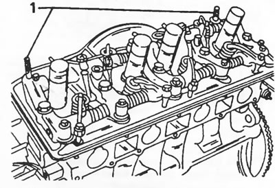
Figure 51. Cylinder head and rocker shaft mounted on the cylinder head. Both guide pins are located at locations (1).
Lubricate the cylinder head bolts with engine oil and screw them into the threaded holes in the cylinder head. If the engine type is not known exactly, they should be measured with a thread gauge. Based on the measurement results, the following should be observed:
- Bolts with M12 thread are tightened with washers.
- Bolts with M11 thread and a lug under the head are tightened without washers.
Tightening of the cylinder head bolts is performed in the sequence shown in Figure 52. The calendar dates for the introduction of modified engines are not the same among different car manufacturers. However, this applies to the following engine types:
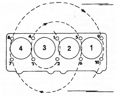
Figure 52. Cylinder head bolt tightening sequence. The diagram applies to all engine types.
| Engine 169V (XM7-T) | until the end of 1986. |
| 170V Motor (XN1-T) | until the end of 1986. |
| Engine 169V (XM7-)) | until April 1989. |
| 170V Engine (XN1-T) | until April 1989. |
| Engine 170C (XN1-TA) | since April 1989. |
| Engine 169V (XM7-T) | since April 1989. |
| Engine 169V (XM7-T) | since April 1989. |
On the above mentioned engines, a change in the tightening method is always accompanied by a change in the engine serial number. For this reason, the data provided can only serve as a general guideline. It is recommended to find out at the service station which group the engine installed in the car belongs to.
Different wrench heads are also required to tighten the bolts, depending on the year of engine production. On engines produced since April 1989, the so-called "Torx 55" head is used in combination with a protractor. For this reason, the following differences should be strictly taken into account:
- On all engine designs, tighten the bolts to a torque of 50 Nm.
- Tighten the rocker arm shaft support nuts on all engines to a torque of 15 Nm.
Until the end of 1986:
- Loosen all bolts in the reverse order shown in Figure 52 and then tighten them in numerical order to a torque of 20 Nm.
- Place the head without a torque wrench on the first bolt, draw a reference line as shown in Figure 53, and tighten the bolt exactly a quarter turn. This corresponds to the 90° shown in the figure. If you position the wrench handle along the engine centerline and turn the wrench until it reaches a transverse position, you get a 90° tightening angle.
- Tighten the remaining bolts in the same manner in the sequence shown in Figure 52.
- If an error was made when tightening the bolts (for example, one bolt is missing), it is necessary to tighten the bolts from the very beginning.
- After a certain mileage, the cylinder head bolts should be tightened as described below.
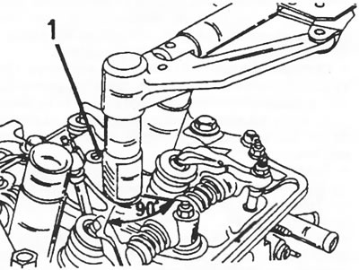
Figure 53. Tightening the cylinder head bolts by 90°. A reference line must be applied.
Since 1986
- Loosen all bolts in the reverse order shown in Figure 52 and then tighten them in numerical order to a torque of 20 Nm.
- Place the socket without a torque wrench on the first bolt, draw a reference line as shown in Figure 54, and tighten the bolt exactly half a turn. This corresponds to the 180° indicated in the figure. If you position the wrench handle along the engine centerline and turn the wrench until it aligns with the same direction but from the opposite side, you'll achieve 180° tightening.
Figure 54 Tightening the cylinder head bolts by 180°. A reference line must be drawn.
- Tighten the remaining bolts in the same manner in the sequence shown in Figure 52.
If an error was made when tightening the bolts (for example, one bolt is missing), it is necessary to tighten the bolts from the very beginning.
After tightening the bolts, they must be retightened as described below, but not after a certain mileage, as for example on engines produced before the end of 1986.
Since April 1989.
These cylinder heads are fitted with what are known as "Torx" size 55 bolts. If the cylinder head bolts are of the type shown in Figure 55, they should be tightened as follows. This requires a protractor, the shape of which can be seen in Figure 55.
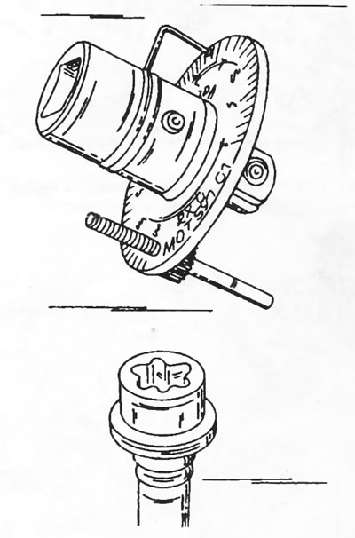
Figure 55. The protractor shown above is used to tighten the bolts. For engines produced since April 1989, where the cylinder head bolts have the appearance shown below, it is necessary to purchase a protractor.
- Insert the bolts. Tighten the bolts by hand in sequence, starting with the inner bolts and moving to the outer ones.
- Tighten the bolts to a torque of 60 Nm according to the sequence shown in Figure 52. To avoid damaging the bolts, use only a Torx 55 key.
- Loosen all bolts and tighten the bolts to a torque of 20 Nm in accordance with the sequence shown in Figure 52.
- After this, in accordance with the sequence shown in Figure 52, tighten the bolts to a certain angle. The tightening angle you should aim for is 300°. If you have a protractor, as shown in Figure 55, tightening is straightforward: tighten the bolt after inserting the wrench head until the protractor's wire pointer reaches 300°. If you don't have a protractor, you should assume that 270° is three-quarters of a turn. You can draw a 90° angle and divide it into six equal sectors. The two sectors make an angle of 30°, which should be added to three quarters of a turn. It may be a bit complicated, but this is the only method that can be offered in the absence of a protractor.
There is no need to tighten the cylinder head on a warm engine or after a certain mileage.
Tightening the cylinder head bolts
As with cylinder head bolt tightening, there are also differences in tightening for different engines.
Until the end of 1986
After the vehicle has driven 2000 km with a new cylinder head gasket, loosen and tighten the bolts again to a torque of 20 Nm in the sequence shown in Figure 52 (one at a time, no more than one bolt at a time).
- As described for tightening, also tighten the bolts by a quarter of a turn.
- Finally, the valve clearances must be adjusted.
Since 1986 (until April 1989.)
There is no need to tighten the cylinder head bolts after a certain mileage. After tightening the bolts as described, tighten them another 35°. Without a protractor, divide the half-turn (180°) into six equal sections and tighten each bolt slightly more than one section. The engine can be cold or warm.
Adjusting the valve clearances on these engines is done when the engine is cold. You should also check the valve clearances after 2000 km.
Since April 1989.
Tightening of the cylinder head bolts on these engines is not required. Adjusting the valve clearances on these engines is done when the engine is cold.
Further assembly of the engine is carried out as follows:
- Adjust valve clearances (section 2.4.5).
- Install the cylinder head cover. Install new spark plug tube seals and O-rings. A new rubber gasket must be glued to the cylinder head cover (rubber glue). Secure the cover with two bolts. Figure 56 shows the installation of the cover with the named parts.
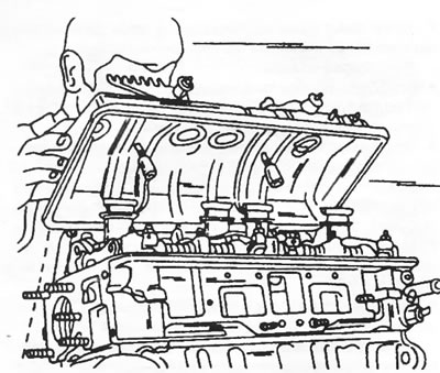
Figure 56. Installing the cylinder head cover.
- From the flywheel side, screw on the oil pipe to lubricate the rocker arm shaft. Screw in the hollow bolts with new sealing rings. If you forget to install the oil pipe shown in Figure 57, no engine oil will be supplied to the rocker shaft.
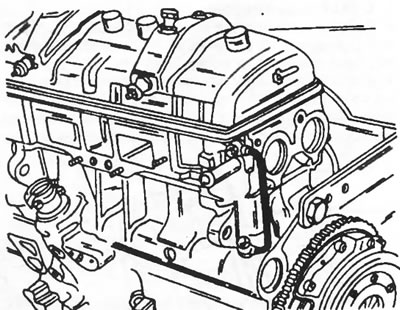
Figure 57. The oil pipe shown on the right is secured with hollow bolts and sealing rings.
- Screw on the oil filter base. The threads of the three bolts should be pre-coated with Loctite. Tighten the bolts to a torque of 13 Nm.
- Lubricate the mating surface of the oil filter with engine oil and screw the filter in until the filter sealing ring is flush with the cylinder block. From this position, manually tighten the oil filter another three-quarters of a turn.
The following is a basic installation of the ignition distributor:
- Align the notch on the belt pulley with the reference mark on the ignition timing adjustment bar, as shown in Figure 58.
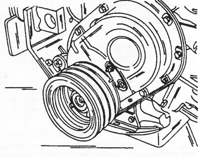
Figure 58. Before installing the ignition distributor, align the cut on the crankshaft belt pulley with the reference mark on the ignition timing adjustment bar.
- Inspect the distributor drive and ensure that the large half of the drive gear is facing the rear of the engine and that the piston of the number one cylinder is at top dead center of the compression stroke. Otherwise, turn the crankshaft one more revolution until the cut is set in the same position.
- Insert the ignition distributor into the engine and set it to the middle position until it locks into place.
- Install the water pump with new rubber seals. Tighten the bolts and nuts to the following torques:
| 8 mm nuts | 22.5 nm |
| Nuts 10 mm | 42.5 nm |
| 10mm bolts | 27.5 nm |
- Finally, install all attachments using Figure 59 and adjust the drive belt tension as described in Section "Cooling system".
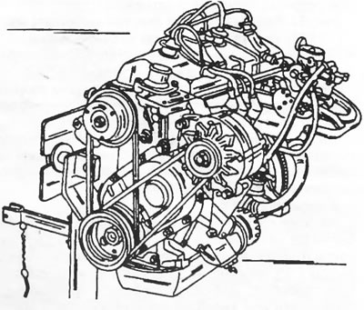
Figure 59. Units and drive belt from the front side of the engine.