



Table of contents: 2.2.1. Removing the cylinder head 🠇 2.2.2. Complete disassembly of the…🠇
The following description applies to all gasoline engines. Before starting work, thoroughly clean all external surfaces of the engine. First, cover all engine openings with clean rags to prevent foreign objects from getting into the engine.
Engine disassembly will be described in detail further in the "Repair and Overhaul" section. This describes tasks that can be performed with the engine both removed and installed, eliminating the need to describe tasks related to a specific disassembly twice. If complete disassembly is required, individual work processes must be combined, and in the specified sequence.
In principle, when disassembling, all moving and movable parts should be marked before removal to ensure their installation in their original position. This is especially important for pistons, valves, bearing caps and bearing shells and applies to all engines. The parts must be folded to avoid confusion during installation.
Under no circumstances should bearing and sealing surfaces be marked with a drafting stamp or, even more so, with a digital stamp. Paint is best for marking parts. It is best to insert the valves into the bottom of an inverted cardboard box, and write their numbers next to the box. Figure 21 shows how easy this is to do. Many of the parts are made of aluminum and require handling accordingly. If, for example, hammer blows are required for removal, a rubber, plastic or leather hammer should be used.
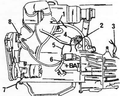
Figure 20. Location of wire connections on the engine and gearbox. 1. Idle air cut-off valve; 2. Temperature sensor; 3. Reversing lights; 4. Coolant temperature sensor; 5. Starter; 6. Alternator; 7. Oil pressure switch; 8. Alternator
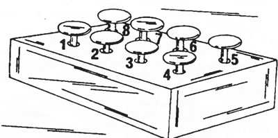
Figure 21. The valves may be installed in the cardboard box as shown to ensure the correct order of installation.
If a dedicated mounting stand is not available, appropriate wooden blocks should be cut to provide access to the top and bottom of the engine mounted on them. After removal, the cylinder head can be clamped in a vice with a metal clamp to which the intake manifold pin bolts are screwed.
The following text will first describe the removal of the cylinder head, as this work will definitely have to be performed at least once during the life of the vehicle. In workshops, some special tools are used for this purpose, but the text provides some possibilities to do without special tools.
2.2.1. Removing the cylinder head
A special wrench head is required to remove the cylinder head. In addition, the engine must be raised in its suspension, that is, a jack with an appropriate gasket must be placed under the engine.
Note: Cylinder head bolts are tightened differently depending on the year of engine production. Before removing the cylinder head, it is necessary to know the exact type and year of manufacture of the engine.
- Disconnect the ground wire from the battery. Move the wire away from the battery so that during work it cannot touch the battery terminal and cause a short circuit.
- Drain the coolant from the cooling system. If the antifreeze looks normal on the outside, drain the coolant into a suitable container. The drain cock is inserted into the radiator, in addition, the plug from the cylinder block should be unscrewed.
- Remove the spare tire from the engine compartment.
- Remove the air intake housing.
- Remove the air filter.
- Disconnect the upper hose from the water pump.
- Disconnect the following hoses connecting the engine (cylinder head) and the body: heater inlet hose, intake manifold heating hose from the cylinder head outlet, intake manifold heating outlet hose from the manifold side and brake booster vacuum hose from the brake booster.
- Disconnect the following parts from the head in the following order: the connectors for the temperature gauge temperature sensor and the second temperature switch. Disconnect the wire from the idle fuel shut-off valve, disconnect the throttle cable and the choke cable. Disconnect the oil supply hose to the rocker arms.
- Unscrew and set aside the diagnostic connector.
- Unscrew the cylinder head cover.
- Remove the spark plug tube seals and pins.
- Remove the alternator together with the drive belt.
- After this, place the front of the vehicle on stands to provide access to the water pump drive belt. Remove the belt by inserting a screwdriver between the belt and the belt pulley as shown in Figure 22 and turning the crankshaft belt pulley with a 35 mm wrench until the belt comes off inward. Be careful not to damage the belt.
- Unscrew the two bolts securing the rear pipe to the water pump. The bolts are located in such a way that they are difficult to find, for which you should use Figure 23.
- Disconnect the muffler pipe from the exhaust manifold as described in engine removal section.
- After this, support the engine from below accordingly (place a jack with a wooden shim under the oil pan) or lift the engine with a suitable cable loop and a hand crane, without blocking access to the cylinder head.
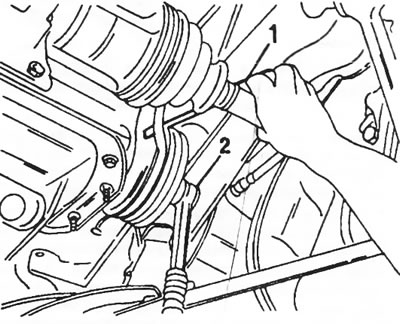
Figure 22. Insert a screwdriver (1) under the drive belt and turn the crankshaft with a ratchet wrench head (2) until the belt comes off.

Figure 23. The arrows indicate the rear tube mounting bolts (above the axle shaft).
- Remove the engine mount shown in Figure 24. To do this, unscrew the two water pump mounting bolts, unscrew the nut (1) in the middle of the engine mount, and remove the aluminum support bracket (2). Before removing, be sure to check that the engine mount is secure.
- In several passes in sequence, starting with the inner and ending with the outer, loosen the head bolts until they are completely unscrewed. Unscrew the five rocker arm shaft mounting nuts and remove or pull out the push rods.
- After this, you can remove the cylinder head. At service stations, two bent lifting levers are used for this purpose, inserted into two holes for the cylinder head bolts. If you make them yourself from an iron rod, the cylinder head is removed from the cylinder block as shown in Figure 25. Rock the cylinder head back and forth until it is freed from the cylinder block. If there are no lifting levers, then you should grab the head at the intake and exhaust manifolds and, by rocking the cylinder head, separate it from the cylinder block. Do not pull the cylinder head straight up, as this may cause the cylinder liners to remain stuck to the head.
- Remove the cylinder head gasket and secure the cylinder liners from the top side with two appropriate clamping strips, as shown in Figure 26.
- Immediately thoroughly clean the surfaces of the cylinder head and cylinder block and carefully remove the remains of the cylinder head gasket with a scraper, without damaging the contact surfaces. Never use sandpaper for cleaning. To prevent any remaining gasket material from getting into the tappet and rocker arm holes, cover all eight holes with balls made from paper handkerchiefs.
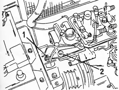
Figure 24. Location of engine mount support on the right side. 1. Engine mount nut; 2. Carrier bracket
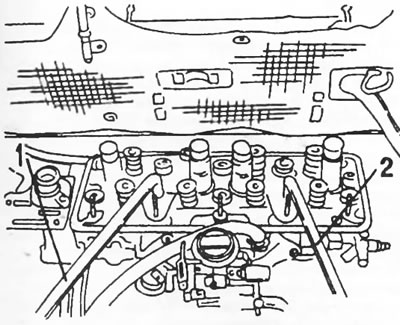
Figure 25. Raising the cylinder head using the two levers (1) and (2) mentioned in the text.
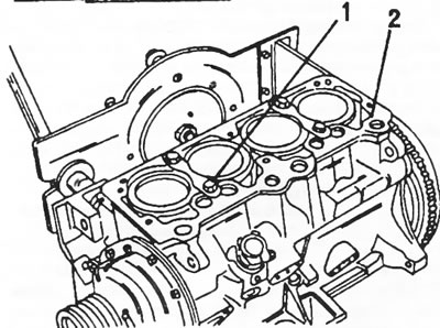
Figure 26. The cylinder liners can be secured to the cylinder block (2) with two clamping strips (1).
Installation of the cylinder head is described in the section describing engine assembly. All removed wires, hoses, etc. are connected in reverse order.
2.2.2. Complete disassembly of the engine
With the engine removed, its disassembly is carried out as follows. It is assumed that the engine is fully assembled.
- Remove the oil filter from one side of the engine. To do this, you should use a special key to unscrew the filter.
- Remove all engine mounted and external parts, namely the cylinder head cover, air heater and exhaust manifold, intake manifold with carburetor, alternator and drive belt, ignition distributor, fuel pump, oil line, wiring harnesses, etc.
- Loosen the five rocker shaft nuts and, in several passes in sequence, starting with the inner ones and ending with the outer ones, loosen the head bolts until they are completely unscrewed. Figure 27 shows the cylinder head after removing the cylinder head cover.
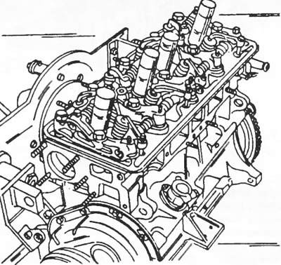
Figure 27. Cylinder head after removing the cylinder head cover.
- Remove the rocker shaft and pull out all the push rods one by one. Mark the push rods accordingly. For example, you can pierce a piece of cardboard with them, on which you write numbers. Number 1 refers to the drive side of the camshaft.
- Remove the cylinder head as shown in Figure 25. Immediately screw the clamping bars to the cylinder block (Figure 26). Otherwise, when the engine is turned over, the cylinder liners may fall out.
- Remove the valve tappets from the holes in the cylinder head. A bar magnet helps a lot with this. Otherwise, you can insert a pointed wooden stick and try to pull out the pushers. The pushers must also be folded in a certain order after removal.
- Unscrew the distributor guide housing. Underneath is the drive shaft, which can now be pulled out.
- While the engine is still upright, the oil pan can be removed. This will prevent oil sediment from getting into the crank mechanism. It is assumed that the oil has already been drained from the engine.
- After this, turn the engine over and unscrew the oil pump in the place shown in Figure 28.
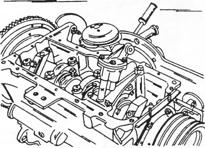
Figure 28. The oil pump is located on the bottom side of the crank mechanism.
- Place a wooden block between one of the crankshaft cheeks and the cylinder block to prevent the crank mechanism from turning and gradually loosen the clutch mounting bolts crosswise, loosening them. Before removing the clutch, mark the relative positions of the clutch housing and flywheel with a punch to ensure subsequent installation of the clutch in its original position (unless the clutch and/or flywheel are being replaced). Remove the driven disk from the flywheel.
- Unscrew the flywheel mounting bolts one by one. There is no need to mark the installation position of the flywheel, since it can only be installed in one position. When unscrewing the bolts, the flywheel should be blocked from turning using the method described above. A firmly stuck flywheel can be knocked out with a rubber hammer. Do not allow the flywheel to fall.
- With the crankshaft locked, loosen the nut on the front of the engine and remove the belt pulley. If necessary, use two pry bars to press the pulley.
- Remove the timing cover.
- Next, the chain tensioner is removed. This is done in different ways, as two different types of tensioners can be installed.
Sedis chain tensioner
- Insert a screwdriver into the hole shown in Figure 29 and press the clamp until it comes off. After this, turn the screwdriver in the direction of the arrow. This locks the ratchet mechanism located below and the chain tensioner remains in a free position.
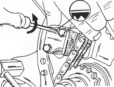
Figure 29. The Sedis chain tensioner has an internal mechanism that must be locked before removal.
Renold chain tensioner
This tensioner does not have a self-locking feature, meaning it must be mechanically locked before being removed from the cylinder block. This requires a piece of wire that is placed around the chain tensioner as shown in Figure 30. Tighten the ends of the wire so that the clamp cannot release from the tensioner.
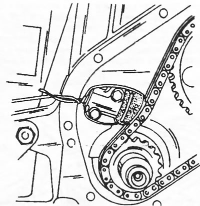
Figure 30 The Renold chain tensioner should be wrapped with a piece of wire before removal.
With all tensioning devices
- Unscrew the two mounting bolts and remove the chain tensioner. The tensioner must be handled with care to ensure that its locking mechanism is not disturbed. There is a rod filter located under the chain tensioner, which should be removed immediately.
- In the order listed, remove the camshaft sprocket, crankshaft sprocket and camshaft. The camshaft sprocket is secured with a bar and three bolts.
Caution: The timing chain does not have installation markings. Therefore, before removal, in case of reinstallation, the chain and both sprockets must be marked with a paint line to ensure their subsequent installation in their previous relative positions.
- Unscrew the rear timing plate.
If the markings are not visible, use a punch to mark the four connecting rod bearing caps and connecting rods (connecting rod bearing No. 1 - one punch strike, No. 2 - two punch strikes, etc.) and unscrew the connecting rod bearing nuts. In this case, turn the crankshaft so that there is access from the top to the two connecting rod bearings to remove their covers. Remove the covers one by one and immediately connect the bearing shells to the covers.
The crank mechanism is shown in Figure 31. Check the markings on the main bearing caps. When viewed from the flywheel side (starting from cover No. 1), the covers should have the following color markings:
- Cover #1 is not marked
- Cover No. 2 is red
- Cover No. 3 is green
- Cover No. 4 white
- Cover No. 5 blue
In addition to the color marking, lids No. 4 and 5, as well as No. 1 and 2, must have their numbers stamped on them. If the markings are not visible, use a punch to mark the four caps accordingly (with a center punch or paint).
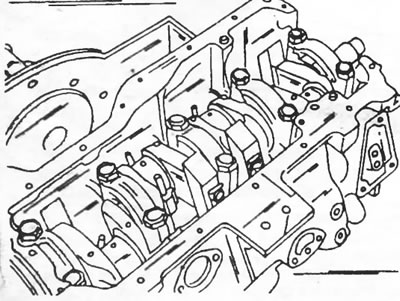
Figure 31. Before unscrewing, check the markings on the crankshaft bearing caps.
- Loosen the cover bolts in several passes, starting from the outer sides and moving towards the middle. Place bearing shells together with bearing caps.
- Pull out the crankshaft and remove the main bearing shells from the main bores. Mark the liners according to their installation position and it is best to stack them together with the bearing caps.
- Unscrew the cylinder liners mounting strips and remove the liners together with the pistons and connecting rods located in them. If the liners are to be re-installed, mark the cylinder numbers on the liners. If any of the sleeves are jammed, lay the cylinder block on its side and knock the sleeve out from the bottom with a wooden drift. After this, remove the pistons and connecting rods from the sleeves. Apply cylinder numbers to the piston crowns.
- Disassemble the pistons and connecting rods as described in section 2.5 "Pistons and connecting rods". However, it is recommended to temporarily bolt the connecting rod bearing caps with liners to the connecting rods. After this, fold them according to Figure 32 on a clean table.
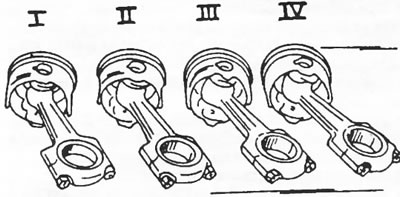
Figure 32. Place the assembled pistons and connecting rods together and write the cylinder number next to each assembly.
- If necessary, disassemble the cylinder head as described in section 2.4 "Cylinder head".
- If work needs to be done on the crankshaft, the counterweights must be removed. Their fastening on the crankshaft is shown in Figure 33. There are plugs on the crankshaft that close the lubrication channels. They should be unscrewed with a rod wrench to ensure that the lubrication channels can be thoroughly cleaned.
- The clutch shaft guide bearing is mounted at the end of the crankshaft (gearbox drive shaft). If a bearing needs to be replaced, a puller is required.
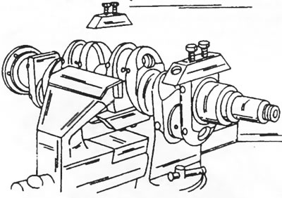
Figure 33. Counterweights are attached to the crankshaft in the manner shown. When removing them, it is necessary to mark their location on the crankshaft.