



Table of contents: Solex 32 PBISA carburettor — 954 and…🠇 Solex 32-34 Z2 and CISAC carburettor…🠇
Solex 32 PBISA carburettor — 954 and 1124 cc models
1. The Soiex PBISA carburettor is a downdraught sing Ie-venturi instrument with a manually-controlled choke (see illustration). The carburettor consists of three main components. These are the upper body, the main body and the throttle body (which contains the throttle valve assembly). An insulating block placed between the carburettor body and throttle body prevents excess heat transfer from the manifold to the main body.
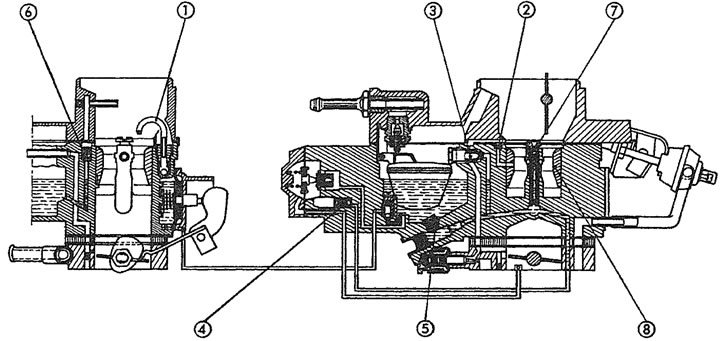
11.1. Sectional view of the Soiex 32 PBISA carburettor fitted to 954 cc and 1124 cc models 1. Accelerator pump tube; 2. Idle ventilator; 3. Idle jet; 4. Enrichment jet; 5. Main jet; 6. Fuel econostat; 7. Air correction jet; 8. Venturi
2. The throttle body contain a drilling through which the engine coolant runs. The engine coolant warms the carburettor body quickly on cold starts, improving atomisation of the fuel/air mixture and preventing carburettor icing during warm-up.
3. During slow running and at idle, fuel from the float chamber passes into the idle channel through a metered idle jet. Here it is mixed with a small amount of air from a calibrated air bleed. The resulting mixture is drawn through a channel, to be discharged from the idle orifice under the throttle valve. A tapered mixture screw is used to vary the outlet, allowing fine control of the idle mixture.
4. A progression slot provides extra enrichment as it is uncovered by the opening of the throttle valve during initial acceleration.
5. Under normal operating conditions, fuel is drawn through a calibrated main jet into the base of the auxiliary venturi. An emulsion tube is placed in the auxiliary venturi, capped with an air correction jet. The fuel is mixed with air, drawn in through the holes in the emulsion tube. The resulting mixture is discharged into the main airstream via four orifices, spaced at 90° apart, in the upper part of the auxiliary venturi.
6. The carburettor also has an accelerator pump to provide an initial spurt of extra fuel during sudden acceleration. The accelerator pump is controlled by a diaphragm and is mechanically operated by a lever and rod which is connected to the throttle linkage.
7. The idle speed is set by an adjustable screw. The adjustable mixture screw is sealed during production with a tamperproof plug, to prevent unnecessary adjustment.
Solex 32-34 Z2 and CISAC carburettor - 1360 cc models
8. The Solex 32-34 Z2 and CISAC carburettors are similar in design and operation and are both downdraught progressive twin-venturi instruments (see illustration). The throttle linkages are arranged so that the secondary throttle valve will not start to open until the primary valve is about two-thirds open, but at full throttle both valves are fully open. The choke control is manual.
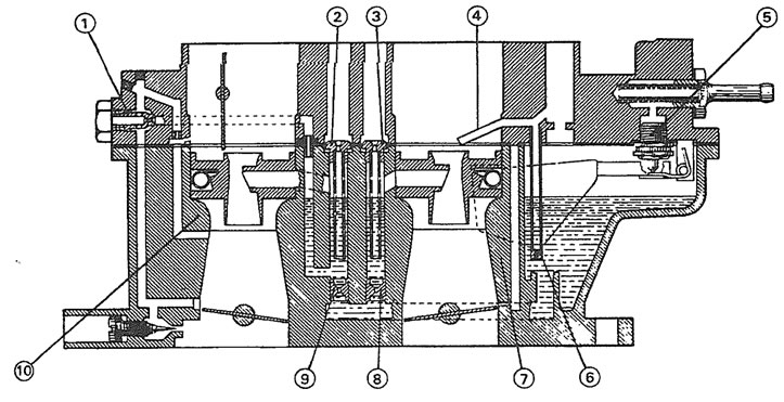
11.8. Sectional view of the Solex 32-34 Z2 carburettor fitted to 1360 cc models 1. Idle jet; 2. Primary air correction jet/emulsion tube; 3. Secondary air correction jet/emulsion tube; 4. Secondary fuel jet; 5. Needle valve; 6. Bypass jet; 7. Secondary venturi; 8. Secondary main jet; 9. Primary main jet; 10. Primary venturi
[Original published on the portal: PeugeotBook]
9. An electrical heating element is fitted to the base of the throttle body. The heater warms the carburettor body quickly on cold starts, improving atomisation of the fuel/air mixture and preventing carburettor icing
10. During slow running and at idle, fuel from the float chamber passes into the idle channel through a metered idle jet. Here it is mixed with a small amount of air from a calibrated air bleed. The resulting mixture is drawn through a channel, to be discharged from the idle orifice under the primary throttle plate. A tapered mixture screw is used to vary the outlet, allowing fine control of the idle mixture.
11. On some models, an idle cut-off valve is used to prevent run-on when the engine is switched off. The valve uses a solenoid plunger to block the idle jet when the ignition is switched off.
12. A progression slot provides extra enrichment as it is uncovered by the opening of the throttle valve during initial acceleration.
13. Under normal operating conditions, the amount of fuel discharged into the airstream is controlled by a calibrated main jet. Fuel is drawn through the main jet. The fuel is then mixed with air, drawn in through the air correction jet and through the holes in the emulsion tube. The resulting mixture is discharged from the main orifice through an auxiliary vent.
14. The carburettor also has an accelerator pump to provide an initial spurt of extra fuel during sudden acceleration. During acceleration, fuel is pumped through a ball valve located in the pump injector and is discharged into both the primary and secondary venturis.
15. The idle speed is set by an adjustable screw. The adjustable mixture screw is sealed during production with a tamperproof plug, to prevent unnecessary adjustment.