



Table of contents: Fault finding 🠇 Overhaul 🠇 Adjustments idle speed and mixture 🠇 Float height setting 🠇 Throttle valve fast idle setting 🠇 Choke pull-down setting 🠇
Fault finding
1. If a carburettor fault is suspected, always check first that the ignition timing is correctly set, that the spark plugs are in good condition and correctly gapped, that the accelerator and choke cables are correctly adjusted and that the air cleaner filter element is clean; refer to the relevant Sections of Chapter 1A, Chapter 5B or this Chapter. If the engine is running very roughly, first check the valve clearances as described in Chapter 2A, then check the compression pressures as described in Chapter 2A.
2. If careful checking of all the above produces no improvement, the carburettor must be removed for cleaning and overhaul.
3. Prior to overhaul, check the availability of component parts before starting work; note that most sealing washers, screws and gaskets are available in kits, as are some of the major sub-assemblies. In most cases, it will be sufficient to dismantle the carburettor and to clean the jets and passages.
Overhaul
Note: Refer to the warning note in Section 1 before proceeding.
4. Remove the carburettor from the vehicle as described in Section 12.
5. Disconnect the vacuum hose from the choke pull-down diaphragm.
6. Disconnect the choke spring (where necessary), then undo the six screws and lift off the carburettor upper body.
7. Tap out the float pivot pin and remove the float assembly, needle valve and float chamber gasket Check that the needle valve anti-vibration ball is free in the valve end, then examine the needle valve tip and seat for wear or damage. Examine the float assembly and pivot pin for signs of wear and damage. The float assembly must be renewed if it appears to be leaking.
8. Unscrew the fuel inlet union and inspect the fuel filter. Clean the filter housing of debris and dirt and renew the filter if it is blocked.
9. Undo the screws, detach the accelerator pump cover and remove the pump diaphragm and spring, noting which way around they are fitted. Examine the diaphragm for signs of damage and deterioration and renew if necessary.
10. Unscrew the idle jet from the main body.
11. Unscrew the main jet from the float chamber. Note that it may be necessary to remove a plug in the float chamber body to expose an opening through which the main jet can be withdrawn.
12. Remove the combined air correction jet and emulsion tube from the auxiliary venturi.
13. Remove the two screws, then separate the carburettor main body and throttle body assemblies. Recover the insulating spacer. Examine the throttle valve spindle and throttle bore for signs of wear or damage and, if necessary, renew the throttle body assembly.
14. Remove the idle mixture adjustment screw tamperproof cap. Screw the screw in until it seats lightly, counting the exact number of turns required to do this, then unscrew and remove it. When refitting, turn the screw in until it seats lightly, then back the screw off by the number of turns noted on removal, to return the screw to its original location.
15. Clean the jets, carburettor body assemblies, float chamber and internal drillings. An air line may be used to clear the internal passages once the carburettor is fully dismantled.
Warning: If high pressure air is directed into drillings and passages where a diaphragm is fitted, the diaphragm is likely to be damaged. Aerosol cans of carburettor cleaner are widely available and can prove very useful in helping to clear internal passages of stubborn obstructions.
16. Use a straight edge to check all carburettor body assembly mating surfaces for distortion.
17. On reassembly, renew any worn components and fit a complete set of new gaskets and seals. A jet kit and a gasket and seal kit, are available from your Peugeot dealer.
18. Reassembly is a reversal of the dismantling procedure. Ensure that all jets are securely locked in position, but take great care not to overtighten them. Ensure that all mating surfaces are clean and dry and that all body sections are correctly assembled with their fuel and air passages correctly aligned. Prior to refitting the carburettor to the vehicle, set the throttle valve fast idle and choke pulldown settings as described below.
Adjustments idle speed and mixture
19. Refer to Chapter 1A.
Float height setting
20. To accurately check the float height setting, a special float height checking gauge is required. Therefore, this task must be entrusted to a Peugeot dealer. As a guide, with the carburettor body inverted (so that the float is at the top and the needle valve is depressed) the distance between the upper edge of the float and the sealing face of the upper body (with its gasket fitted) should be approximately 38 mm. To adjust the float height setting, carefully bend the pivot arm.
Throttle valve fast idle setting
21. Invert the carburettor and operate the carburettor choke linkage to fully close the choke valve. The fast idle screw will butt against the fast idle cam and force open the throttle valve slightly.
22. Using the shank of an appropriate diameter twist drill, measure the clearance between the edge of the throttle valve and bore and compare this to the specified clearance given in the Specifications. If necessary, adjust by turning the fast idle adjustment screw in the appropriate direction until the specified clearance is obtained (see illustration).
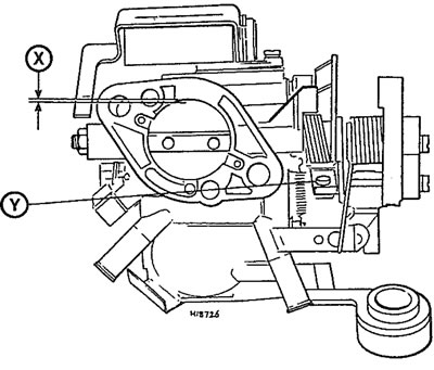
13.22. Throttle valve fast idle setting - Solex 32 PBISA carburettor fitted to 954 cc and 1124 cc models Adjust screw Y until clearance X is as given in the Specifications
Choke pull-down setting
23. Operate the carburettor choke linkage to fully close the choke valve and hold the linkage in this position.
24. Attach a hand-held vacuum pump to the choke pull-down diaphragm and apply a vacuum to the diaphragm so that the diaphragm rod is pulled fully into the diaphragm body. In the absence of a vacuum pump, the rod can be pushed into the diaphragm using a small screwdriver.
25. With the rod fully retracted, use the shank of a suitable twist drill to measure the clearance between the edge of the choke valve and bore and compare this to the specified clearance given in the Specifications. If necessary, remove the plug from the diaphragm cover and adjust by turning the adjustment screw (see illustration). Once the pull-down setting is correctly adjusted, refit the plug to the diaphragm cover and remove the vacuum pump (where used).
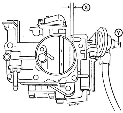
13.25. Choke pull-down setting - Solex 32 PBISA carburettor fitted to 954 cc and 1124 cc models Adjust screw Y until clearance X is as given in the Specifications