



Fault finding
1. Refer to Section 13.
Overhaul
Note: Refer to the warning note in Section 1 before proceeding.
2. Remove the carburettor from the vehicle as described in Section 12.
3. Unscrew the idle cut-off solenoid from the carburettor body and remove it along with its plunger and spring. To test the solenoid, connect a 12-volt battery to it (positive terminal to the solenoid terminal, negative terminal to the solenoid body) and check that the plunger is retracted fully into the body. Disconnect the battery and check that the plunger is pushed out by spring pressure. If the valve does not perform as expected and cleaning does not improve the situation, the solenoid valve must be renewed.
4. Remove the five screws and lift off the carburettor upper body.
5. Tap out the float pivot pin and remove the float assembly, needle valve and float chamber gasket Check that the needle valve anti-vibration ball is free in the valve end, then examine the needle valve tip and seat for wear or damage. Examine the float assembly and pivot pin for signs of wear and damage. The float assembly must be renewed if it appears to be leaking - shake the float to detect the presence of fuel inside.
6. Unscrew the fuel inlet union and inspect the fuel filter. Clean the filter housing of debris and dirt and renew the filter if it is blocked.
7. Undo the four screws, detach the accelerator pump cover and remove the pump diaphragm and spring, noting which way around they are fitted. Examine the diaphragm for signs of damage and deterioration and renew if necessary. Remove the choke pulldown diaphragm and part-load enrichment diaphragms and examine them in the same way.
8. Unscrew the idle jet from the upper body.
9. Unscrew both the primary and secondary combined air correction jets and emulsion tubes.
10. Using a long thin screwdriver, unscrew the main jets from the bottom of the emulsion tube drillings. Invert the carburettor and catch the jets as they fall out of the drillings.
11. Remove the idle mixture adjustment screw tamperproof cap. Screw the screw in until it seats lightly, counting the exact number of turns required to do this, then unscrew it. On refitting, screw the screw in until it seats lightly, then back the screw off by the number of turns noted on removal, to return the screw to its original position.
12. Examine the carburettor components as described in paragraphs 15 to 17 of Section 13.
13. To test the carburettor heating element, connect a multimeter, set to the resistance function, between the heater wiring terminal and the carburettor body. A resistance reading of approximately 0.25 to 0.5 ohms should be obtained. If an open-circuit is present, or an extremely high resistance reading is obtained, it is likely that the heating element is faulty. To remove the element, undo the retaining screw and plate, then slide the element noting the correct locations of the insulators positioned on each side of the element.
14. Reassembly is a reversal of the dismantling procedure. Ensure that all jets are securely locked in position, but take great care not to overtighten them. Ensure all mating surfaces are clean and dry and that all body sections are correctly assembled with their fuel and air passages correctly aligned. If the heating element has been disturbed, ensure that the insulators are correctly fitted so that the element is in no danger of contacting the carburettor body. Prior to refitting the carburettor to the vehicle, set the float height, throttle valve fast idle and choke pull-down settings as described below.
Adjustments
Idle speed and mixture
15. Refer to Chapter 1A.
Float height setting
16. To accurately check the float height setting, a special float height checking gauge is required. Therefore, this task must be entrusted to a Peugeot dealer. As a guide, with the carburettor body inverted (so that the float is at the top and the needle valve is depressed) the distance between the upper edge of the float and the sealing face of the upper body (with its gasket fitted) should be approximately 35 mm.
17. If necessary the float height can be adjusted by carefully bending the small tang on the float arm which contacts the needle valve.
Throttle valve fast idle setting
18. Invert the carburettor and pull the carburettor choke linkage to fully close the choke valve. The fast idle screw will butt against the fast idle cam and force the throttle valve open slightly.
19. Using the shank of a twist drill, measure the clearance between the edge of the throttle valve and bore and compare this to the clearance given in the Specifications at the start of this Chapter, if necessary, adjust by turning the fast idle adjustment screw in the appropriate direction until the specified clearance is obtained (see illustration).
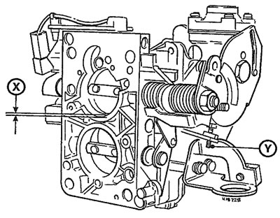
14.19. Throttle valve fast idle setting - Solex 32-34 Z2 carburettor fitted to 1360 cc models Adjust screw Y until clearance X is as given in the Specifications
Choke pull-down setting
20. Pull the carburettor choke linkage to fully close the choke valve and hold the linkage in this position.
21. Attach a hand-held vacuum pump to the choke pull-down diaphragm and apply a vacuum to the diaphragm so that the diaphragm rod is pulled fully into the diaphragm body. In the absence of a vacuum pump, the rod can be pushed into the diaphragm with a small screwdriver.
22. With the rod fully retracted, use the shank of a twist drill to measure the clearance between the edge of the choke valve and bore and compare this to the clearance given in the Specifications (see iliustration). If necessary, remove the plug from the diaphragm cover and adjust by turning the adjustment screw. Once the pull-down setting is correctly adjusted, refit the plug to the diaphragm cover and remove the vacuum pump (where used).
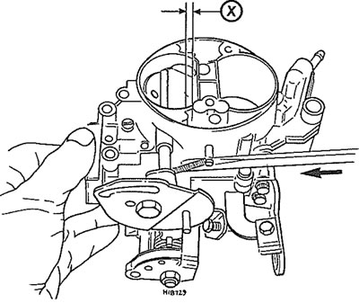
14.22. Choke pull-down setting(using a screwdriver to retract the diaphragm rod) - Solex 32-34 Z2 carburettor fitted to 1360 cc models Adjust as ahown in text until clearance X is as given in the Specification
[Original text is located at: PeugeotBook]