



Table of contents: Selection of bearing shells 🠇 Big-end bearing running clearance…🠇 Final piston/connecting rod refitting 🠇
Selection of bearing shells
1. There are two sizes of big-end bearing shell produced by Peugeot; a standard size for use with the standard crankshaft, and an undersize for use once the crankshaft journals have been reground. When ordering shells, quote the diameter of the crankshaft big-end crankpins, to ensure that the correct set of shells are purchased.
2. Prior to refitting the piston/connecting rod assemblies, it is recommended that the bigend bearing running clearance is checked as follows.
Big-end bearing running clearance check
3. Clean the backs of the bearing shells, and the bearing locations in both the connecting rod and bearing cap.
4. Press the bearing shells into their locations, ensuring that the tab on each shell engages in the recess in the connecting rod and cap (see illustration). Take care not to touch any shell's bearing surface with your fingers. If the original bearing shells are being used for the check, ensure that they are refitted in their original locations. The clearance can be checked in either of two ways.
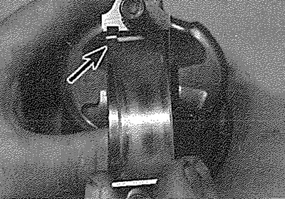
18.4. Fitting a bearing shell to a connecting rod - ensure that the tab (arrowed) engages with the recess in the connecting rod
5. One method is to refit the big-end bearing cap to the connecting rod, ensuring that they are fitted the correct way round (see paragraph 19), with the bearing shells in place. With the cap retaining nuts correctly tightened, use an internal micrometer or vernier caliper to measure the internal diameter of each assembled pair of bearing shells. If the diameter of each corresponding crankshaft journal is measured and then subtracted from the bearing internal diameter, the result will be the big-end bearing running clearance.
6. The second, and more accurate, method is to use Plastigage (see Section 17).
7. Ensure that the bearing shells are correctly fitted. Place a strand of Plastigage on each (cleaned) crankpin journal.
8. Refit the (clean) piston/connecting rod assemblies to the crankshaft, and refit the big-end bearing caps, using the marks made or noted on removal to ensure that they are fitted the correct way round.
9. Tighten the bearing cap nuts as described below in paragraph 20. Take care not to disturb the Plastigage, nor to rotate the connecting rod during the tightening sequence.
10. Dismantle the assemblies without rotating the connecting rods. Use the scale printed on the Plastigage envelope to obtain the big-end bearing running clearance.
11. If the clearance is significantly different from that expected, the bearing shells may be the wrong size (or excessively worn, if the original shells are being re-used). Make sure that no dirt or oil was trapped between the bearing shells and the caps or connecting rods when the clearance was measured. If the Plastigage was wider at one end than at the other, the crankpins may be tapered.
12. Note that Peugeot do not specify a recommended big-end bearing running clearance. The figure given in theSpecifications is a guide figure, which is typical for this type of engine. Before condemning the components concerned, refer to your Peugeot dealer or engine reconditioning specialist for further information on the specified running clearance. Their advice on the best course of action to be taken can then also be obtained.
13. On completion, carefully scrape away all traces of the Plastigage material from the crankshaft and bearing shells. Use your fingernail, or some other object which is unlikely to score the bearing surfaces.
Final piston/connecting rod refitting
Note: Refer to Section 19 for the correct selection of pistons on TUD 5 engines.
14. Note that the following procedure assumes that the cylinder liners (where fitted) are in position in the cylinder block/crankcase as described in Section 11, and that the crankshaft and main bearing ladder/caps are in place (see Section 17). It is possible to fit the pistons to the liners before fitting the liners to the cylinder block; the advantage of using this method is that the pistons enter the liner from the bottom end, which is tapered to allow easy entry of the piston rings (a piston ring compressor will still be required).
15. Ensure that the bearing shells are correctly fitted as described in paragraphs 3 and 4. If new shells are being fitted, ensure that all traces of the protective grease are cleaned off using paraffin. Wipe dry the shells and connecting rods with a lint-free cloth.
16. Lubricate the cylinder bores/liners, the pistons, and piston rings, then lay out each piston/connecting rod assembly in its respective position.
17. Start with assembly No 1. Make sure that the piston rings are still spaced as described in Section 16, then clamp them in position with a piston ring compressor.
18. Insert the piston/connecting rod assembly into the top of cylinder/liner No 1 as follows:
- a) On diesel engines, ensure that the 'cloverleaf cutout on the piston crown faces the oil filter side of the cylinder block.
- b) On DOHC 16-valve petrol engines, ensure that the valve head cutouts on the piston crown face the side of the cylinder block opposite the oil filter.
- c) On SOHO 8-valve petrol engines, ensure that the arrow on the piston crown is pointing towards the timing belt end of the engine.
Using a block of wood or hammer handle against the piston crown, tap the assembly into the cylinder/liner until the piston crown is flush with the top of the cylinder/liner (see illustration).
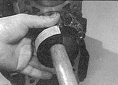
18.18. Tap the piston into the bore using a hammer handle
19. Ensure that the bearing shell is still correctly installed. Liberally lubricate the crankpin and both bearing shells. Taking care not to mark the cylinder/liner bores, tap the piston/connecting rod assembly down the bore/liner and onto the crankpin. Refit the big end bearing cap, tightening its retaining nuts finger-tight at first. Note that the faces with the identification marks must match (which means that the bearing shel! locating tabs abut each other).
20. Tighten the bearing cap retaining nuts evenly and progressively to the specified torque setting (see illustration).
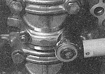
18.20. Tighten the big-end bearing cap nuts to the specified torque setting
21. Rotate the crankshaft. Check that it turns freely; some stiffness is to be expected if new components have been fitted, but there should be no signs of binding or tight spots.
22. Refit the remaining three piston/ connecting rod assemblies in the same way. Note: On engines with wet liners, clamp down the liners before turning the crankshaft (see Chapter 2B, Section 11, paragraph 20).
23. Refit the cylinder head, oil pump and sump as described in Part A or B of this Chapter (as applicable).