



Table of contents: Selection of new bearing shells 🠇 Diesel engine 🠇 Main bearing running clearance check 🠇 Cast-iron block engine 🠇 Final crankshaft refitting 🠇 Cast-iron block engine 🠇
Selection of new bearing shells
Petrol engines
1. To ensure that the main bearing running clearance can be accurately set, the bearing shells are supplied in different thicknesses (grades).
2. On cast iron block engines there are three different grades of bearing shell, on aluminium block engines there are three different grades on early engines and six different grades on later engines. The grades are indicated by a colour-coding marked on the edge of each shell, which denotes the shell's thickness, as listed in the following table. The upper shell on all bearings is of the same size (class B, colour code black), and the running clearance is controlled by fitting a lower bearing shell of the required thickness.
Aluminium block engine - early models
| Bearing colour code | Thickness (mm) | |
| Standard | Undersize | |
| Blue (class A) | 1.823 | 1.973 |
| Black (class B) | 1.835 | 1.985 |
| Green (class C) | 1.848 | 1.998 |
Aluminium block engine - later models
| Bearing colour | Thickness code (mm) | |
| Standard | Undersize | |
| Blue (class A) | 1.823 | 1.973 |
| Orange (class B) | 1.829 | 1.979 |
| Black (class C) | 1.835 | 1.985 |
| Yellow (class D) | 1.841 | 1.991 |
| Green (class E) | 1.847 | 1.998 |
| White (class F) | 1.853 | 2.003 |
Cast-iron block engine
| Bearing colour code | Thickness (mm) | |
| Standard | Undersize | |
| Blue (class A) | 1.844 | 1.994 |
| Black (class B) | 1.858 | 2.008 |
| Green (class C) | 1.869 | 2.019 |
3. New bearing shells can be selected using the reference marks on the cylinder block/crankcase. The cylinder block marks identify the diameter of the bearing bores and the crankshaft marks, the diameter of the crankshaft journals.
4. The cylinder block reference marks are on the right-hand (timing belt) end of the block, and the crankshaft reference marks are on the right-hand (timing belt) end of the crankshaft, on the right-hand web of No 4 crankpin (see illustration). These marks can be used to select bearing shells of the required thickness as follows.
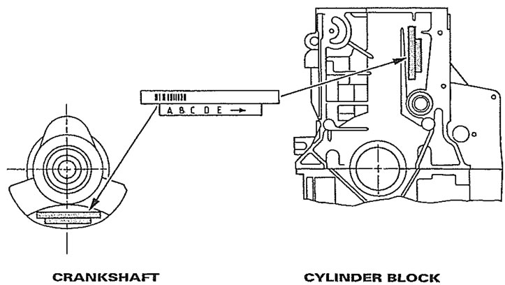
17.4. Cylinder block and crankshaft main bearing reference markings
5. On both the crankshaft and block there are two lines of identification: a bar code, which is used by Peugeot during production, and a row of five letters. The first letter in the sequence refers to the size of No 1 bearing (at the flywheel/driveplate end). The last letter in the sequence (which is followed by an arrow) refers to the size of No 5 main bearing. These marks can be used to select the required bearing shell grade as follows.
6. Obtain the identification letter of both the relevant crankshaft journal and the cylinder block bearing bore. Noting that the cylinder block letters are listed across the top of the chart, and the crankshaft letters down the side, trace a vertical line down from the relevant cylinder block letter, and a horizontal line across from the relevant crankshaft letter, and find the point at which both lines cross. This crossover point will indicate the grade of lower bearing shell required to give the correct main bearing running clearance. For example, illustration 17.6a shows cylinder block reference G, and crankshaft reference T, crossing at a point within the area of Class A, indicating that a blue-coded (Class A) lower bearing shell is required to give the correct main bearing running clearance (see illustrations).
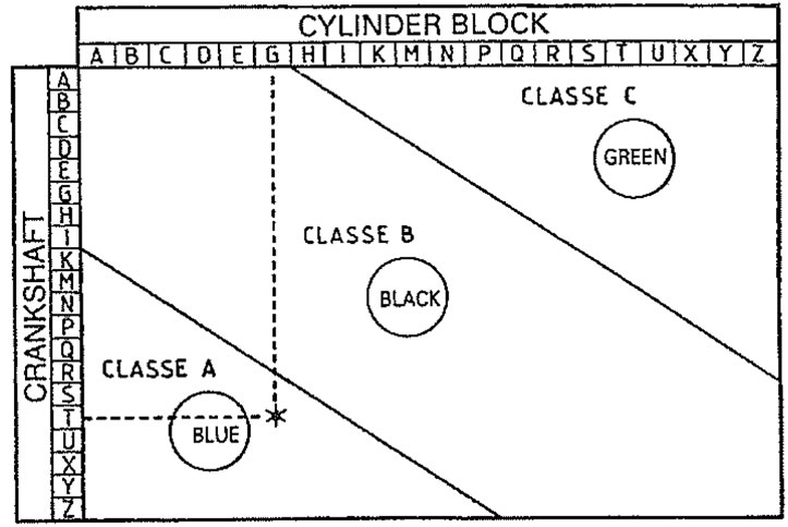
17.6a. Three class main bearing shell selection chart - see text
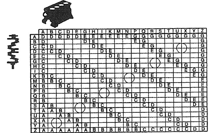
17.6b. Six class main bearing shell selection chart - see text
7. Repeat this procedure so that the required bearing shell grade is obtained for each of the five main bearing journals.
8. Seek the advice of your Peugeot dealer for the latest information on parts availability when ordering new bearing shells.
Diesel engine
9. The procedure is the same as that described in paragraphs 1 to 8. However, when the different grades were initially introduced, it was only possible to get blue-coded (Class A) lower bearing shells. This has now been extended, and it is now possible to get blue and black-coded lower bearing shells (Class A and B). Green-coded (Class C) lower bearing shells are not available.
Main bearing running clearance check
Aluminium block engines
10. On early engines, if the modified bearing shells are to be fitted, obtain a set of new black (Class B) upper bearing shells and new blue (Class A) lower bearing shells. On later engines where the modified bearing shells are already fitted, the running clearance check can be carried out using the original bearing shells. However, it is preferable to use a new set, since the results obtained will be more conclusive.
11. Clean the backs of the bearing shells, and the bearing locations in both the cylinder block/crankcase and the main bearing ladder.
12. Press the bearing shells into their locations, ensuring that the tab on each shell engages in the notch in the cylinder block/crankcase or main bearing ladder location. Take care not to touch any shell's bearing surface with your fingers. Note that the grooved bearing shells, both upper and lower, are fitted to Nos 2 and 4 main bearings (see illustration). If the original bearing shells are being used for the check, ensure that they are refitted in their original locations. The clearance can be checked in either of two ways.
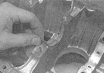
17.12. Note that the grooved bearing shells are fitted to Nos 2 and 4 main bearing journals
13. One method (which will be difficult to achieve without a range of internal micrometers or internal/external expanding calipers) is to refit the main bearing ladder casting to the cylinder block/crankcase, with the bearing shells in place. With the casting retaining bolts correctly tightened, measure the internal diameter of each assembled pair of bearing shells, if the diameter of each corresponding crankshaft journal is measured and then subtracted from the bearing internal diameter, the result will be the main bearing running clearance.
14. The second (and more accurate) method is to use an American product known as "Plastigage". This consists of a fine thread of perfectly-round plastic, which is compressed between the bearing shell and the journal. When the shell is removed, the plastic is deformed, and can be measured with a special card gauge supplied with the kit. The running clearance is determined from this gauge. Plastigage should be available from your Peugeot dealer; otherwise, enquiries at one of the larger specialist motor factors should produce the name of a stockist in your area. The procedure for using Plastigage is as follows.
15. With the main bearing upper shells in place, carefully lay the crankshaft in position.
Do not use any lubricant; the crankshaft journals and bearing shells must be perfectly clean and dry.
16. Cut several lengths of the appropriate-size Plastigage (they should be slightly shorter than the width of the main bearings), and place one length on each crankshaft journal axis (see illustration).
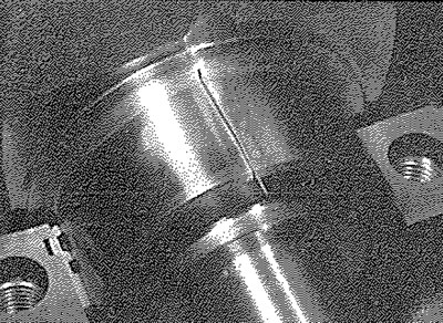
17.16. Plastigage in place on a crankshaft main bearing journal
17. With the main bearing lower shells in position, refit the main bearing ladder casting, tightening its retaining bolts as described in paragraph 31. Take care not to disturb the Plastigage, and do not rotate the crankshaft at any time during this operation.
18. Remove the main bearing ladder casting, again taking great care not to disturb the Plastigage or rotate the crankshaft.
19. Compare the width of the crushed Plastigage on each journal to the scale printed on the Plastigage envelope, to obtain the main bearing running clearance (see illustration). Compare the clearance measured with that given in the Specifications at the start of this Chapter.
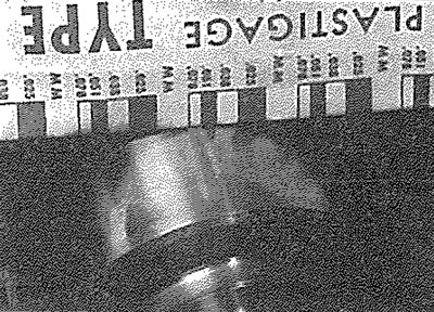
17.19. Measuring the width of the deformed Plastigage using the scale on the card provided
20. If the clearance is significantly different from that expected, the bearing shells may be the wrong size (or excessively worn, if the original shells are being re-used). Before deciding that different-size shells are required, make sure that no dirt or oil was trapped between the bearing shells and the main bearing ladder or block when the clearance was measured. If the Plastigage was wider at one end than at the other, the crankshaft journal may be tapered.
21. If the clearance is not as specified, use the reading obtained, along with the shell thicknesses quoted above, to calculate the necessary grade of bearing shells required. When calculating the bearing clearance required, bear in mind that it is always better to have the running clearance slightly towards the lower end of the specified range, to allow for wear in use.
22. Where necessary, obtain the required grades of bearing shell, and repeat the running clearance checking procedure as described above.
23. On completion, carefully scrape away all traces of the Plastigage material from the crankshaft and bearing shells. Use your fingernail, or a wooden or plastic scraper which is unlikely to score the bearing surfaces.
Cast-iron block engine
24. The procedure is similar to that described in the previous paragraphs for the aluminium block engine, except that each main bearing has a separate cap, which must be fitted and the bolts tightened to the specified torques.
Final crankshaft refitting
Aluminium block engines
25. Carefully lift the crankshaft out of the cylinder block once more.
26. Using a little grease, stick the upper thrustwashers to each side of the No 2 main bearing upper location; ensure that the oilway grooves on each thrustwasher face outwards (away from the cylinder block) (see illustration).
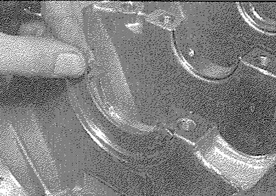
17.26. Refitting a crankshaft thrustwasher
27. Place the bearing shells in their locations as described earlier. If new shells are being fitted, ensure that all traces of protective grease are cleaned off using paraffin. Wipe dry the shells and connecting rods with a lint-free cloth. Liberally lubricate each bearing shell in the cylinder block/crankcase with clean engine oil (see illustration).
You can find the original on the resource [www.PEUGEOTBOOK.ru]
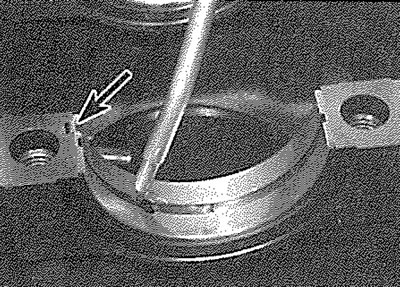
17.27. Ensure each bearing shell tab (arrowed) is correctly located and lubricate the shell with clean engine oil
28. Refit the Woodruff key, then slide on the oil pump drive sprocket, and locate the drive chain on the sprocket (see illustration). Lower the crankshaft into position so that Nos 2 and 3 cylinder crankpins are at TDC; Nos 1 and 4 cylinder crankpins will be at BDC, ready for fitting No 1 piston. Check the crankshaft endfloat as described in Section 13.
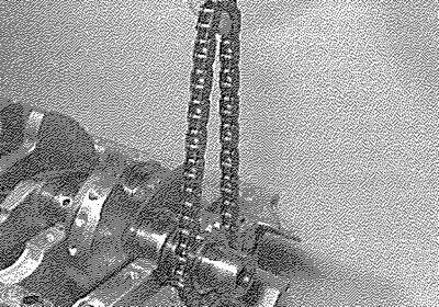
17.28. Refitting the oil pump drive chain and sprocket
29. Thoroughly degrease the mating surfaces of the cylinder block/crankcase and the main bearing ladder. Apply a thin bead of suitable sealant to the cylinder block/crankcase mating surface of the main bearing ladder casting, then spread to an even film (see illustration).
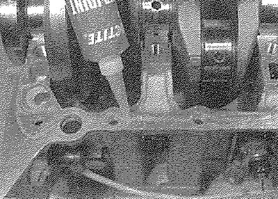
17.29. On aluminium block engines, apply a thin film of sealant to the cylinder block/crankcase mating surface...
30. Lubricate the lower bearing shells with clean engine oil, then refit the main bearing ladder, ensuring that the shells are not displaced, and that the locating dowels engage correctly (see illustration).
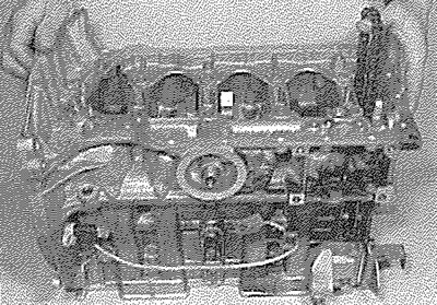
17.30. ... then lower the main bearing ladder into position
31. Install the ten 11 mm main bearing ladder retaining bolts, and tighten them all by hand only. Working progressively outwards from the centre bolts, tighten the ten bolts, by a turn at a time, to the specified Stage 1 torque wrench setting. Once all the bolts have been tightened to the Stage 1 setting, angle-tighten the bolts through the specified Stage 2 angle using a socket and extension bar. It is recommended that an angle-measuring gauge is used during this stage of the tightening, to ensure accuracy (see illustrations). If a gauge is not available, use a dab of white paint to make alignment marks between the bolt head and casting prior to tightening; the marks can then be used to check that the bolt has been rotated sufficiently during tightening.
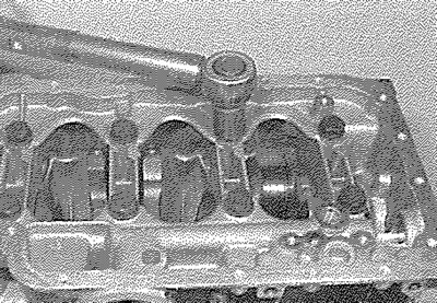
17.31a. Tighten the ten 11 mm main bearing bolts to the Stage 1 torque setting...
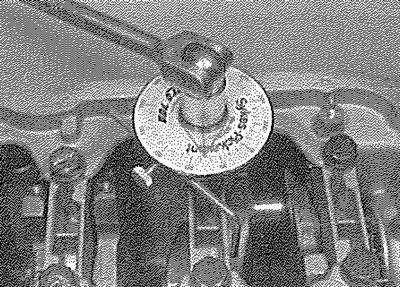
17.31b.... then angle-tighten them through the specified Stage 2 angle
32. Refit all the 6 mm bolts securing the main bearing ladder to the base of the cylinder block, and tighten them to the specified torque. Check that the crankshaft rotates freely.
33. Refit the piston/connecting rod assemblies to the crankshaft as described in Section 18.
34. Ensuring that the drive chain is correctly located on the sprocket, refit the oil pump and sump as described in Part A or B (as applicable) of this Chapter.
35. Fit two new crankshaft oil seals as described in Part Part A (as applicable).
36. Refit the flywheel as described in Part A of this Chapter (as applicable).
37. Where removed, refit the cylinder head as described in Part A or B (as applicable). Also refit the crankshaft sprocket and timing belt as described in Part A or Part B (as applicable).
Cast-iron block engine
38. Carefully lift the crankshaft out of the cylinder block once more.
39. Using a little grease, stick the upper thrustwashers to each side of the No 2 main bearing upper location. Ensure that the oilway grooves on each thrustwasher face outwards (away from the cylinder block).
40. Place the bearing shells in their locations as described earlier. If new shells are being fitted, ensure that all traces of protective grease are cleaned off using paraffin. Wipe dry the shells and connecting rods with a lint-free cloth. Liberally lubricate each bearing shell in the cylinder block/crankcase and cap with clean engine oil.
41. Lower the crankshaft into position so that Nos 2 and 3 cylinder crankpins are at TDC; Nos 1 and 4 cylinder crankpins will be at BDC, ready for fitting No 1 piston. Check the crankshaft endfloat as described in Section 13.
42. Lubricate the lower bearing shells in the main bearing caps with clean engine oil. Make sure that the locating lugs on the shells engage with the corresponding recesses in the caps.
43. Fit the main bearing caps to their correct locations, ensuring that they are fitted the correct way round (the bearing shell lug recesses in the block and caps must be on the same side). Insert the bolts loosely.
44. Tighten the main bearing cap bolts to the specified Stage 1 torque wrench setting (see illustration). Once all the bolts have been tightened to the Stage 1 setting, angle-tighten the bolts through the specified Stage 2 angle, using a socket and extension bar. It is recommended that an angle-measuring gauge is used during this stage of the tightening, to ensure accuracy. If a gauge is not available, use a dab of white paint to make alignment marks between the bolt head and casting prior to tightening; the marks can then be used to check that the bolt has been rotated sufficiently during tightening.
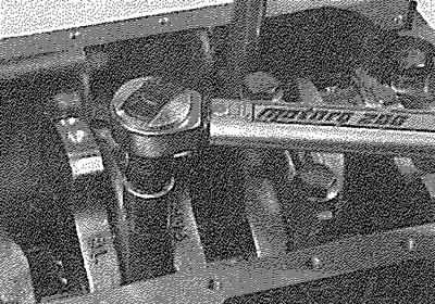
17.44. On cast-iron block engines, tighten the main bearing cap retaining bolts to the specified Stage 1 torque
45. Check that the crankshaft rotates freely.
46. Refit the piston/connecting rod assemblies to the crankshaft as described in Section 18.
47. Refit the Woodruff key to the crankshaft groove, and slide on the oil pump drive sprocket. Locate the drive chain on the sprocket.
48. Ensure that the mating surfaces of front oil seal housing and cylinder block are clean and dry. Note the correct fitted depth of the front oil seal then, using a large flat-bladed screwdriver, lever the seal out of the housing.
49. Apply a smear of suitable sealant to the oil seal housing mating surface, and make sure that the locating dowels are in position. Slide the housing over the end of the crankshaft, and into position on the cylinder block. Tighten the housing retaining bolts securely.
50. Repeat the operations in paragraphs 48 and 49, and fit the rear oil seal housing.
51. Fit a new front and rear crankshaft oil seal as described in Part A of this Chapter (as applicable).
52. Ensuring that the chain is correctly located on the drive sprocket, refit the oil pump and sump as described in Part A or B of this Chapter (as applicable).
53. Refit the flywheel as described in Part A of this Chapter (as applicable).
54. Where removed, refit the cylinder head and install the crankshaft sprocket and timing belt as described in the relevant Sections of Part A or B (as applicable).