



Removal
1. Disconnect the battery negative terminal (refer to "Disconnecting the battery").
2. Drain the cooling system as described in Chapter 1B.
3. Align the engine assembly/valve timing holes as described in Section 3, and lock the camshaft sprocket, injection pump sprocket and flywheel in position. Do not attempt to rotate the engine whilst the locking tools are in position.
4. Loosen the timing belt tensioner pulley retaining nut. Rotate the pulley in a clockwise direction, using a suitable square-section key fitted to the hole in the pulley hub, then retighten the retaining nut.
5. Disengage the timing belt from the camshaft sprocket, and move the belt clear, taking care not to bend or twist it sharply.
6. Working as described in the relevant Section of Chapter 4D, carry out the following operations:
- a) Remove the air intake duct.
- b) Remove the inlet manifold.
- c) Disconnect the exhaust system front pipe from the exhaust manifold.
- d) Disconnect the fast idle cable from the injection pump (so that the valve is free to be removed with the head).
- e) Remove the injector pipes.
7. Loosen the retaining clip, and disconnect the vacuum pipe from the braking system vacuum pump located on the left-hand end of the cylinder head (see illustration).
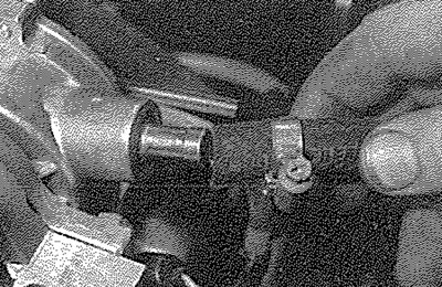
11.7. Slacken the retaining clip, and disconnect the hose from the braking system vacuum pump
8. Release the retaining clips, and disconnect the coolant hoses from the fuel filter/thermostat housing, noting their fitted positions (see illustrations).
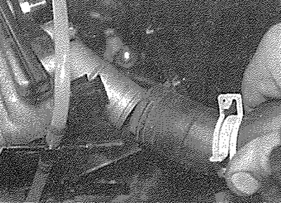
11.8a. Disconnect the coolant hoses from the front...
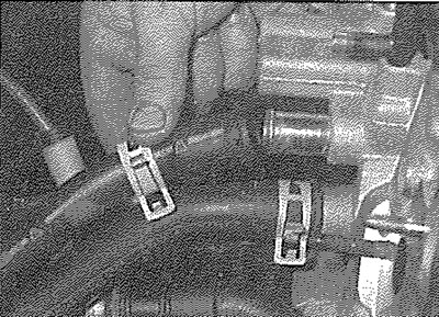
11.8b.... and rear of the fuel filter/thermostat housing
9. Slacken the retaining clips, and disconnect the fuel supply hose and pump feed hose from the fuel filter/thermostat housing, which is mounted onto the left-hand end of the cylinder head (see illustration). Where the original crimped-type Peugeot hose clips are still fitted, cut and discard them. Use standard worm-drive clips on refitting.
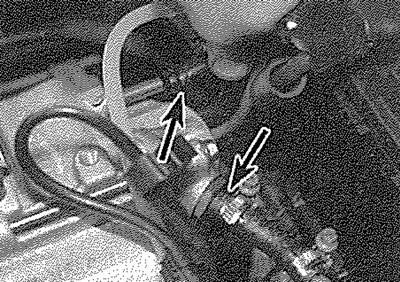
11.9. Disconnect the fuel supply and pump feed hoses (arrowed) from the fuel filter/thermostat housing
10. Disconnect the fuel return pipe from No 1 cylinder injector, and position the pipe clear of the head so that it will not hinder removal.
11. Unscrew the retaining nut and disconnect the feed wire from No 1 cylinder glow plug (see illustration). Screw the nut back onto the plug, for safe-keeping, and tighten it securely.
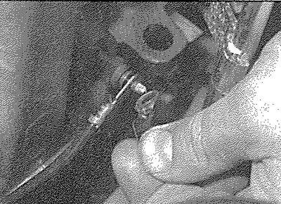
11.11. Slacken the retaining nut and disconnect the feed wire from No 1 cylinder glow plug
12. Disconnect the wiring from the temperature sender located on the front left-hand end of the cylinder head (see illustration).
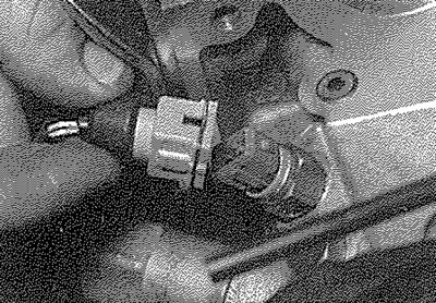
11.12. Disconnect the wiring connector from the temperature sender unit...
13. Unscrew the bolt securing the engine oil dipstick tube to the front of the cylinder head (see illustration).
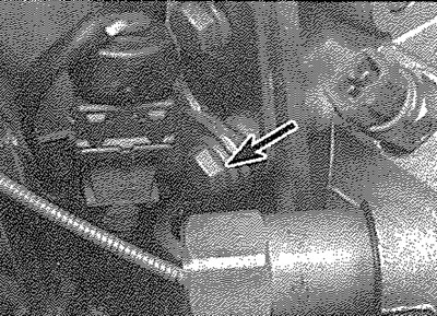
11.13. ... and unscrew the dipstick tube retaining bolt (arrowed)
14. Remove the cylinder head cover as described in Section 4.
15. Starting on the outside and working inwards in a spiral sequence, progressively loosen the cylinder head bolts, a half a turn at a time. Use the reverse sequence shown in paragraph 34 of this Section.
16. Lift out the cylinder head bolts, and recover the washers.
17. The joint between the cylinder head and gasket and the cylinder block/crankcase must now be broken. This is particularly important on TUD 3 engines as there is a risk of disturbing the seal at the bottom of the wet liners. Although these liners are better located and sealed than on some other wet-liner engines, there is still a risk of coolant and foreign matter leaking into the sump if the cylinder head is lifted carelessly. If care is not taken and the liners are moved, there is also a possibility of the bottom seals being disturbed, causing leakage after refitting the head.
18. To break the joint, obtain two L-shaped metal bars which fit into the cylinder head bolt holes. Gently "rock" the cylinder head free towards the front of the car (see illustration 12.21 in Part A of this Chapter). Do not try to swivel the head on the cylinder block/crankcase; it is located by dowels, as well as by the tops of the liners.
19. When the joint is broken, lift the cylinder head away; seek assistance if possible, as it is a heavy assembly. Remove the gasket from the top of the block, noting the two locating dowels. If the locating dowels are a loose fit, remove them and store them with the head for safe-keeping. Do not discard the gasket - it will be needed for identification purposes.
20. On TUD 3 engines, do not attempt to rotate the crankshaft with the cylinder head removed, otherwise the wet liners may be displaced. Operations that require the rotation of the crankshaft (eg cleaning the piston crowns), should only be carried out once the cylinder liners are firmly clamped in position (see illustration). In the absence of the special Peugeot liner clamps, the liners can be clamped in position using large flat washers positioned underneath suitable-length bolts. Alternatively, the original head bolts could be temporarily refitted, with suitable spacers fitted to their shanks.
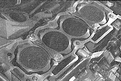
11.20. On TUD 3 engines, the cylinder liners must be clamped in position before the crankshaft is rotated
21. If the cylinder head is to be dismantled for overhaul, remove the camshaft and followers as described in Section 9, then refer to Part C of this Chapter.
Preparation for refitting
22. The mating faces of the cylinder head and cylinder biock/crankcase must be perfectly clean before refitting the head. Use a hard plastic or wood scraper to remove ail traces of gasket and carbon; also clean the piston crowns. Refer to paragraph 20 before turning the crankshaft. Take particular care during the cleaning operations, as the soft aluminium alloy is damaged easily. Also, make sure that the carbon is not allowed to enter the oil and water passages - this is particularly important for the lubrication system, as carbon could block the oil supply to the engine's components. Using adhesive tape and paper, seal the water, oil and bolt holes in the cylinder biock/crankcase. Clean all the pistons in the same way.
23. Check the mating surfaces of the cylinder biock/crankcase and the cylinder head for nicks, deep scratches and other damage. If slight, they may be removed carefully with a file, but if excessive, machining may be the only alternative to renewal.
24. If warpage of the cylinder head gasket surface is suspected, use a straight-edge to check it for distortion. Refer to Part C of this Chapter if necessary.
25. When purchasing a new cylinder head gasket, it is essential that a gasket of the correct thickness is obtained. There are two different thicknesses available - the standard gasket which is fitted at the factory, and a slightly thicker "repair" gasket (+ 0.1 mm), for use once the head gasket face has been machined. The gasket type can be identified as described in the following paragraph, using the cut-outs on the left-hand end of the gasket (see illustration 12.29 in Part A of this Chapter).
26. With the gasket fitted the correct way up on the cylinder block, there will be two cutouts at the rear of the left-hand side of the gasket identifying the engine type (i.e. TUD engine). In the centre of the gasket, there may be another series of between 0 and 4 cutouts, identifying the manufacturer of the gasket and whether or not it contains asbestos (these cut-outs are of little importance). The important cut-out iocation is at the front of the gasket; on the standardthickness gasket, there will be no cut-out in this position, whereas on the thicker "repair" gasket, there will be a single cut-out. Identify the gasket type, and ensure that the new gasket obtained is of the correct thickness. If there is any doubt as to which gasket is fitted, take the old gasket along to your Peugeot dealer, and have him confirm the gasket type.
27. The manufacturers recommend that the cylinder head bolts are measured, to determine whether renewal is necessary. Measure the length of each bolt (without the washer fitted) from the underside of the head to the end of the bolt. If any one bolt is greater than specified length (refer to the Specifications), all of the bolts should be renewed as a complete set. As there have been numerous revisions to the bolt types on these engines, it is advisable to consult a Peugeot dealer as to the latest recommendations. Considering the stress which the cylinder head bolts are under, it is highly recommended that they are renewed, regardless of their apparent condition.
28. On TUD 3 engines, prior to refitting the cylinder head, check the cylinder liner protrusion as described in Part C of this Chapter.
Refitting
29. Wipe clean the mating surfaces of the cylinder head and cylinder block/crankcase. Check that the two locating dowels are in position at each end of the cylinder block/ crankcase surface and, if necessary, remove the cylinder liner clamps (see illustration).
Note: Ensure that the exhaust manifold is in position, as this can not be refitted with the head in position without disturbing the right hand engine mounting (see Chapter 4D). On TUD 5 engines, clean the threads in the cylinder block with a M10x150 tap.
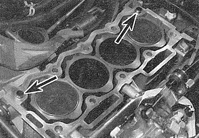
11.29. Ensure that the locating dowels (arrowed) are in position...
Data published on the website [www.PeugeotBook.ru]
30. Position a new gasket on the cylinder biock/crankcase surface (makers name facing upwards), ensuring that its identification cutouts are at the left-hand end of the gasket (see illustration).
Note: Left- and right-hand are as seen from the driver's seat, throughout this manual.
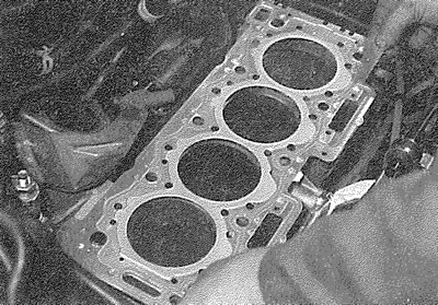
11.30. ... and fit a new gasket
31. Check that the flywheel, injection pump sprocket and camshaft sprocket are still correctly locked in position then, with the aid of an assistant, carefully refit the cylinder head assembly to the block, aligning it with the locating dowels (see illustration).
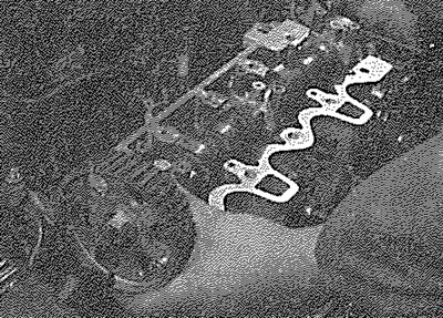
11.31. Ensure that all sprockets are correctly positioned, then refit the cylinder head assembly
32. Apply a smear of grease to the threads, and to the underside of the heads, of the cylinder head bolts. Peugeot recommend the use of Molykote G Rapid Plus grease (available from your Peugeot dealer - a sachet is supplied with the top-end gasket set); in the absence of the specified grease, a goodquality high-melting-point grease may be used (see illustration).
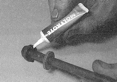
11.32. Apply a smear of the specified grease to the underside of the heads and to the threads of all cylinder head bolts
33. Carefully enter each bolt and washer into its relevant hole (do not drop them in) and screw in, by hand only, until finger-tight (see illustration).
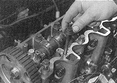
11.33. Screw the head bolts into position
34. Working progressively and in the sequence shown, tighten the cylinder head bolts to their Stage 1 torque setting, using a torque wrench and suitable socket (see illustrations).
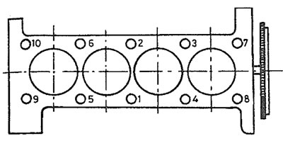
11.34a. Head bolt tightening sequence for TUD 3 engine
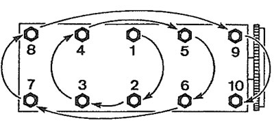
11.34b. Head bolt tightening sequence for TUD 5 engine
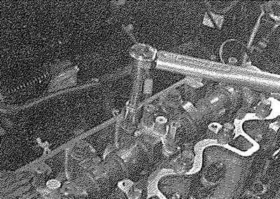
11.34c. Tighten the head bolts through the various torque settings...
35. On TUD 5 engines using an angle gauge, tighten the bolts in the same sequence to the specified Stage 2 setting, then continue on to paragraph 38.
36. On TUD 3 engines, fully slacken the bolts, in the reverse order of tightening. Working again in the given sequence, tighten them to the specified Stage 2 torque setting. Once all the bolts have been tightened to their Stage 2 setting, working again in the specified sequence, angle-tighten the bolts through the specified Stage 3 angle, using a socket and extension bar. It is recommended that an angle-measuring gauge is used during this stage of the tightening, to ensure accuracy (see Illustration).
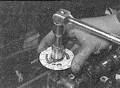
11.36. ... and angle settings as described in text
37. With all bolts tightened through the specified Stage 3 angle, repeat the procedure and tighten the bolts through the specified Stage 4 angle setting.
38. With the cylinder head bolts correctly tightened, refit the dipstick tube retaining bolt, and tighten it securely.
39. Connect the wiring connector to the cylinder head temperature sender unit.
40. Connect the feed wire to No 1 cylinder glow plug, and securely tighten its retaining nut.
41. Ensure that all pipes and hoses are correctly routed, reconnect the fuel and coolant hoses to the filter/thermostat housing, and secure them in position with their retaining clips.
42. Connect the return pipe to No 1 cylinder injector ensuring that the pipe is correctly routed.
43. Connect the vacuum pipe to the braking system pump.
44. Carry out the following operations as described in Chapter 4D:
- a) Refit the injector pipes, and tighten the union nuts to the specified torque.
- b) Reconnect and adjust the fast idle cable.
- c) Reconnect the exhaust system to the manifold.
- d) Refit the inlet manifold.
- e) Refit the intake duct.
45. With the crankshaft, injection pump and camshaft locked in position, refit the timing belt to the camshaft sprocket. Ensure that the belt is taut around the crankshaft sprocket, idler pulley and injection pump sprocket, so that any slack is on the tensioner pulley side of the belt Do not twist the belt sharply while refitting it, and ensure that the belt teeth are seated centrally in the sprockets.
46. Loosen the tensioner pulley retaining nut. Rotate the pulley anti-clockwise to remove all free play from the timing belt, then retighten the nut.
47. Tension the belt as described under the relevant sub-heading of Section 6.
48. Check and, if necessary, adjust the valve clearances as described in Section 10.
49. Refit the cylinder head cover as described in Section 4.
50. Refill the cooling system as described in Chapter 1B.
51. Reconnect the battery negative terminal, then prime and bleed the fuel system as described in Chapter 4D.