



Note: This is not a routine operation. It should only be necessary at high mileage, after overhaul, or when investigating noise or power loss which may be attributable to the valve gear. Shims are available in thicknesses between 3.20 mm and 4.90 mm, in steps of 0.025 mm. On certain models the shims are located under the tappets, therefore if adjustment is necessary, the camshaft will have to be removed.
1. The importance of having the valve clearances correctly adjusted cannot be overstressed, as they vitally affect the performance of the engine. That being said, the check should not be regarded as routine maintenance, and should only be carried out when the valve gear has become noisy, after engine overhaul, or when trying to trace the cause of power loss which may be attributed to the valve gear. The clearances are checked as follows, noting that the engine must be cold for the check to be accurate.
2. Chock the rear wheels then jack up the front of the vehicle and support it on axle stands (see "Jacking and vehicle support"). Remove the right-hand front road wheel.
3. The engine can then be turned over using a suitable socket and extension bar fitted to the crankshaft sprocket bolt. Where necessary, undo the retaining nut and free the coolant hoses from the bracket to improve access further.
4. Remove the cylinder head cover as described in Section 4.
5. Draw the outline of the engine on a piece of paper, numbering the cylinders 1 to 4 (No 1 cylinder is at the transmission end of the engine). Show the position of each valve, together with the specified valve clearance (see paragraph 9). Above each valve, draw two lines for noting the actual clearance and the amount of adjustment required.
6. Turn the crankshaft until the inlet valve of No 1 cylinder (nearest the transmission) is fully closed, with the tip of the cam facing directly away from the cam follower.
7. Using feeler blades, measure the clearance between the base of the cam and the follower (see illustration). Record the clearance on the paper.
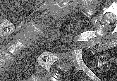
10.7. Checking a valve clearance
8. Repeat the measurement for the other seven valves, turning the crankshaft as necessary so that the cam lobe in question is always facing directly away from the relevant follower.
9. Calculate the difference between each measured clearance and the desired value, and record it on the piece of paper. Since the clearance is different for inlet and exhaust valves, make sure that you are aware which valve you are dealing with. The valve locations can be determined from the position of the manifolds.
10. Where a valve clearance differs from the specified value, then the shim for that valve must be replaced with a thinner or thicker shim accordingly.
11. To remove the shim, the follower has to be pressed down against valve spring pressure just far enough to allow the shim to be slid out. To do this, make sure that the cam lobe of the valve on which the shim is to be removed is pointing away from the follower, then rotate the follower so that its notch is at a right-angle to the camshaft centre-line.
12. Using a suitable C-spanner or stout screwdriver, carefully lever down between the camshaft and the edge of the follower, until the follower is depressed sufficiently to allow the shim to be slid out of position.
13. With the shim removed, slowly release the follower. If difficulty is experienced in removing the shims, it will be necessary to remove the camshaft as described in Section 9.
14. The shim size is stamped on the bottom face of the shim, but it is advisable to use a micrometer to measure the true thickness of any shim removed, as it may have been reduced by wear (see illustrations). The size of shim required is calculated as follows.
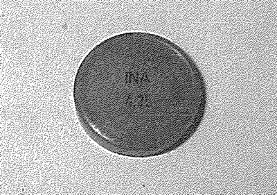
10.14a. Shim thickness is stamped on the bottom face of the shim...
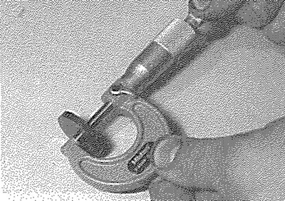
10.14b.... however, shims should be measured to determine their true thickness
15. If the measured clearance is less than specified, subtract the measured clearance from the specified clearance, and subtract the result from the thickness of the existing shim.
For example:
Sample calculation - inlet valve clearance too small
- Clearance measured = 0.10 mm
- Desired clearance = 0.15 mm
- Difference = 0.05 mm
- Shim thickness fitted = 3.70 mm
- Shim thickness reqd. =3.70 - 0.05 = 3.65 mm
16. If the measured clearance is greater than specified, subtract the specified clearance from the measured clearance, and add the result to the thickness of the existing shim.
For example:
Sample calculation - exhaust valve clearance too big
- Clearance measured = 0.40 mm
- Desired clearance = 0.30 mm
- Difference = 0.10 mm
- Shim thickness fitted = 3.45 mm
- Shim thickness reqd. = 3.45 + 0.10 = 3.55 mm
17. Depress the follower, then slide the required size shim into position, with its marked face facing downwards. Ensure that the shim is correctly seated, then repeat the procedure (as required) for the remaining valve which require adjustment
18. Once all valves have been adjusted, rotate the crankshaft through at least four complete turns in the correct direction of rotation, to settle all disturbed shims in position, then recheck the clearances as described above.
19. With all valve clearances correctly adjusted, refit the cylinder head cover as described in Section 4.
20. Refit the roadwheel, then lower the vehicle to the ground and tighten the wheel bolts to the specified torque setting (see Chapter 1B Specifications). Refit the glow plugs, where applicable (see Chapter 5C). Where necessary, clip the coolant hoses into position, and securely tighten the bracket retaining nut.