



Table of contents: General information 🠇 Removal 🠇 Refitting 🠇 TUD 3 engines 🠇 TUD 5 engines 🠇 Tensioning without the special…🠇 Tensioning using the special…🠇
Note: Peugeot specify the use of a special electronic tool (SEEM belt tensioning measuring tool) to correctly set the timing belt tension. On TUD 3 engines and If access to this equipment cannot be obtained, an approximate setting can be achieved using the method described below. If the method described is used, the belt tension must be checked using the special electronic tool at the earliest possible opportunity. Do not drive the vehicle over large distances, or use high engine speeds, until the belt tension is known to be correct. Refer to a Peugeot dealer for advice.
General information
1. The timing belt drives the camshaft, injection pump, and coolant pump from a toothed sprocket on the front of the crankshaft. If the belt breaks or slips in service, the pistons are likely to hit the valve heads, resulting in extensive (and expensive) damage.
2. The timing belt should be renewed at the specified intervals, or earlier if it is contaminated with oil, or at all noisy in operation (a "scraping" noise due to uneven wear).
3. If the timing belt is being removed, it is a wise precaution to check the condition of the coolant pump at the same time (check for signs of coolant leakage). This may avoid the need to remove the timing belt again at a later stage, should the coolant pump fail.
Removal
4. Disconnect the battery negative terminal (refer to "Disconnecting the battery").
5. Align the engine assembly/valve timing holes, then lock the crankshaft, camshaft and fuel injection pump sprockets in position as described in Section 3. Do not attempt to rotate the engine whilst the locking tools are in position.
6. Remove the lower timing belt cover as described in Section 5.
7. Remove the right-hand headlight unit as described in Chapter 12.
8. Loosen the timing belt tensioner pulley retaining nut. Pivot the pulley in a clockwise direction, using a square-section key fitted to the hole in the pulley hub, then retighten the retaining nut.
9. Slip the belt off the sprockets, idler and tensioner, and remove it from the engine.
10. Check the timing belt carefully for any signs of uneven wear, splitting, or oil contamination. Pay particular attention to the roots of the teeth. Renew the belt if there is the slightest doubt about its condition. If the engine is under-going an overhaul, and has covered more than 36 000 miles (60 000 km) with the existing belt fitted, renew the belt as a matter of course, regardless of its apparent condition. The cost of a new belt is nothing when compared to the cost of repairs, should the belt break in service. If signs of oil contamination are found, trace the source of the oil leak, and rectify it. Wash down the engine timing belt area and all related components, to remove all traces of oil.
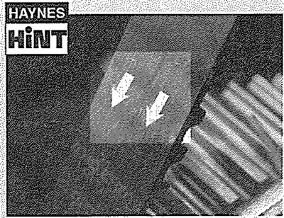
If the timing belt is to be re-used, use white paint or similar to mark the direction of rotation on the belt (if markings do not already exist).
Refitting
11. Prior to refitting, thoroughly clean the timing belt sprockets. Check that both the tensioner and idler pulleys rotate freely, without any sign of roughness. If necessary, renew the damaged pulley as described in Section 7. Make sure that the locking tools are still in place, as described in Section 3.
TUD 3 engines
12. Manoeuvre the timing belt into position, ensuring that the arrows on the belt are pointing in the direction of rotation (clockwise when viewed from the right-hand end of the engine). Do not twist the timing belt sharply while refitting it.
13. First locate the belt over the crankshaft sprocket then, keeping the belt taut, feed it over the idler pulley, around the injection pump sprocket, and over the camshaft sprocket (see illustration). Locate the belt over the tensioner pulley, then finally over the coolant pump sprocket. Ensure that the belt teeth are seated centrally in the sprockets, and that any slack is in the section of the belt between the camshaft and coolant pump sprockets.
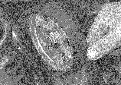
6.13. Engage the timing belt with the sprockets as described in text
14. Loosen the tensioner pulley retaining nut. Pivot the pulley anti-clockwise to remove all freeplay from the timing belt, then retighten the nut (see illustration). Tension the timing belt as described under the relevant subheading.
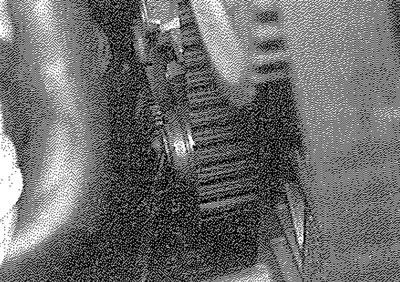
6.14. Remove all freeplay from the belt, then securely tighten the tensioner pulley retaining nut
TUD 5 engines
15. Slacken the six (three on each) camshaft and injection pump hub bolts (see illustration). Ensure that the sprockets move freely on their hubs. Finger tighten the six sprocket hub bolts, then slacken them all by just under a quarter of a turn.
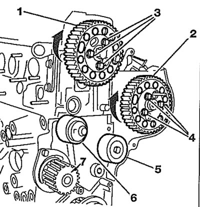
6.15. Camshaft and injection pump sprocket hub bolts (TUD 5 engines) 1. Camshaft sprocket; 2. Injection pump sprocket; 3. Camshaft sprocket hub bolts; 4. Injection pump sprocket hub bolts; 5. Tension roller; 6. Tension roller; 7. Coolant pump sprocket
16. Move the camshaft and injection pump sprockets to the bottom of their slot, by turning them in the direction of engine rotation (clockwise).
17. Locate the timing belt, fully taut, firstly on the crankshaft sprocket, then on the tension roller nearest to the injection pump. Wrap the belt around the injection pump sprocket, ensuring that the belt does not "jump" on the crankshaft sprocket. If necessary move the injection pump sprocket, anti-clockwise by no more than one tooth to enable the belt to seat properly.
18. Fit the belt on the camshaft sprocket in the same way. Feed the belt around the remaining tension roller and on around the coolant pump sprocket. Continue on to paragraph 28.
Tensioning without the special electronic measuring tool
Note: If this method is used, ensure that the belt tension is checked by a Peugeot dealerat the earliest possible opportunity.
19. Peugeot dealers use a special tool to tension the timing belt (see illustration 6.14 in Part A of this Chapter). A similar tool may be fabricated using a suitable square-section bar attached to an arm made from a metal strip; a hole should be drilled in the strip at a distance of 80 mm from the centre of the square-section bar. Fit the tool to the hole in the tensioner pulley, keeping the tool arm as close to the horizontal as possible, and hang a 2.0 kg (4.4 lb.) weight from the hole in the tool. In the absence of an object of the specified weight, a spring balance can be used to exert the required force, ensuring that the spring balance is held at 90° to the tool arm (see illustration). Slacken the pulley retaining nut, allowing the weight or force exerted (as applicable) to push the tensioner pulley against the belt. Now push down on the tool to exert some additional force, and retighten the pulley nut. This effectively "over-tensions" the belt, to allow it to settle in before the final tensioning.
6.19. Using a home-made special tool and spring balance to tension the timing belt
20. If this special tool is not available, an approximate setting may be achieved by pivoting the tensioner pulley anti-clockwise until it is just possible to turn the timing belt through 45° by finger and thumb, midway between the camshaft and injection pump sprockets. Once the belt has been tensioned, securely tighten the pulley retaining nut.
21. Remove the locking tools from the camshaft sprocket, injection pump sprocket and flywheel.
22. Using a suitable socket and extension bar on the crankshaft sprocket bolt, rotate the crankshaft through four complete rotations in a clockwise direction (viewed from the righthand end of the engine). Do not at any time rotate the crankshaft anti-clockwise.
23. Allow the belt to stand for approximately one minute, then slacken the tensioner pulley nut.
24. Where the special tool is being used, allow the weight of the tool to tension the belt, then tighten the pulley retaining nut to the specified torque. Do not exert any extra force on the tool this time (as in paragraph 15).
25. Where tensioning is being carried out without the special tool, re-tension the belt as described in paragraph 16, then tighten the tensioner pulley nut to the specified torque.
Note: This method is only an initial setting. Do not drive the vehicle over large distances, or use high engine speeds, until the belt tension is known to be correct.
26. Rotate the crankshaft through a further two turns clockwise, and check that the camshaft sprocket, injection pump and flywheel timing holes are still correctly aligned.
27. If all is well, refit the timing belt covers as described in Section 5, then refit the headlight as described in Chapter 12.
Tensioning using the special electronic measuring tool
28. Fit the special belt tensioning measuring equipment to the "front run" of the timing belt, midway between the camshaft and injection pump sprockets. Position the tensioner pulley so that the belt is tensioned to "Stage 1" of the specified setting, then retighten its retaining nut without moving the tensioner.
29. On TUD 5 engines, ensure that the camshaft and injection sprocket hub bolts are located in the centre of the slot (see illustration). If they are at either end, refit the timing belt. Fully tighten all six bolts to their correct torque.
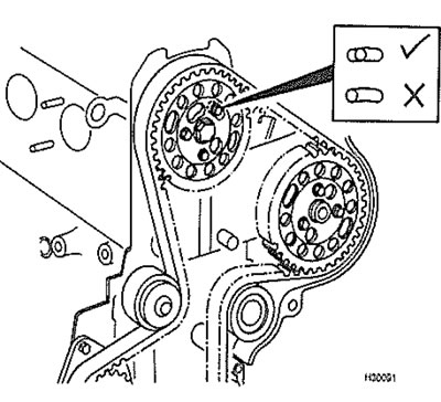
6.29. Correct location of camshaft and injection pump sprocket hub bolts (TUD 5 engines)
30. Remove the locking tools from the camshaft sprocket, injection pump sprocket and flywheel, and remove the measuring tool from the belt.
31. Using a socket and extension bar on the crankshaft sprocket bolt, rotate the crankshaft through four (two on TUD 5 engines) complete rotations in a clockwise direction (viewed from the right-hand end of the engine). Do not at any time rotate the crankshaft anti-clockwise.
32. Refit the locking tools and allow the belt to stand for approximately one minute, then slacken the tensioner pulley retaining nut (and six sprocket hub bolts), and refit the measuring tool to the belt. Position the tensioner pulley so that the belt is tensioned to the "Stage 2" setting, then tighten the pulley retaining nut to the specified torque setting. On TUD 5 engines tighten the six camshaft and injection pump hub sprockets bolts.
33. Remove the measuring tool from the belt. Then on TUD 3 engines, rotate the crankshaft through another two complete rotations in a clockwise direction, so that the camshaft and injection pump sprocket and flywheel timing holes are realigned. Do not at any time rotate the crankshaft anti-clockwise. Refit the measuring tool to the belt and check that the belt tension is as specified at the 'Final stage'.
Original can be viewed at [Peugeotbook.ru]
34. If the belt tension is incorrect, repeat the procedures in paragraphs 32 and 33.
35. With the belt tension correctly set, remove the locking tools if applicable and refit the timing belt covers as described in Section 5. Refit the headlight (if applicable) as described in Chapter 12.