



Caution: Do not attempt to rotate the engine whilst the crankshaft, camshaft or injection pump are locked in position. If the engine is to be left in this state for a long period of time, it is a good idea to place warning notices inside the vehicle, and in the engine compartment. This will reduce the possibility of the engine being accidentally cranked on the starter motor, which is likely to cause damage with the locking tools in place.
All engines
1. Timing holes are drilled in the camshaft sprocket, injection pump sprocket (or, on TUD5 engines, in their hubs) and in the flywheel. The holes are used to ensure that the crankshaft, camshaft and injection pump are correctly positioned when assembling the engine (to prevent the possibility of the valves contacting the pistons when refitting the cylinder head), or refitting the timing belt. When the timing holes are aligned with access holes, Suitable-diameter pins or bolts can be inserted to lock the camshaft, injection pump sprocket and crankshaft in position, preventing them from rotating. Proceed as follows.
Note: With the timing holes aligned, No 4 cylinder is at TDC on its compression stroke.
2. Remove the upper and centre timing belt covers as described in Section 5.
3. The crankshaft must now be turned until the timing holes in the camshaft sprocket and injection pump sprocket (or their hubs) are aligned with the corresponding holes in the cylinder head and pump mounting bracket (or body). The holes are aligned when the camshaft sprocket hole is in the 4 o'clock position, when viewed from the right-hand end of the engine. The crankshaft can be turned by using a spanner on the crankshaft sprocket bolt, noting that it should always be rotated in a clockwise direction (viewed from the right-hand end of the engine). If necessary, firmly apply the handbrake then jack up the front of the car, support it on axle stands (see "Jacking and vehicle support") and remove the right-hand roadwheel and wheel arch liner (see chapter 11, section 23) to improve access to the crankshaft pulley.
4. With the camshaft sprocket (or its hub) hole correctly positioned, insert a 6 mm diameter bolt or drill bit through the hole in the front left-hand flange of the cylinder block, and locate it in the timing hole in the flywheel (see illustrations). Note that it may be necessary to rotate the crankshaft slightly, to get the holes to align.
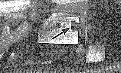
3.4a. Insert a 6 mm bolt or locking pin (arrowed) through hole in cylinder block flange and into timing hole in the flywheel - TUD 3 engine...
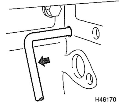
3.4b.... and TUD 5 engine
TUD 3 engines
5. With the flywheel correctly positioned, insert an 8 mm diameter bolt through the timing hole in the camshaft sprocket, and screw it into the hole on the cylinder head. Also insert an 8 mm diameter bolt through each of the two timing holes on the injection pump sprocket, and screw them into the holes in the mounting bracket (see illustrations).
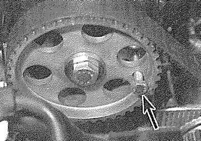
3.5a. Insert an 8 mm bolt (arrowed) through the camshaft sprocket timing hole, and screw it into the cylinder head...
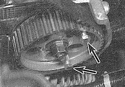
3.5b.... then insert two 8 mm bolts (arrowed) into the injection pump sprocket holes and screw them into the mounting bracket
6. The crankshaft, camshaft and injection pump are now locked in position.
TUD 5 engines
7. With the flywheel correctly positioned, insert an 8 mm diameter bolt through the slot of the camshaft sprocket, along the groove in the hub and screw it into the cylinder head. Also insert an 6 mm diameter pin or drill bit through the slot of the injection pump sprocket, along the groove in the hub, into the hole on the sump body.
8. The crankshaft, camshaft and injection pump are now locked in position.
Caution: On TUD 5 engines, the only way of ensure that the injection pump timing is correct is to lock the engine at TDC, as above. The sprocket hub timing must be perfectly aligned with the grooves corresponding holes in the cylinder head and pump body, so that there is minimum displacement when the locking bolt is put into place. An additional check wilt be required when the timing belt is put back on (see section 6).