



Note: Some BE 4/5 gearboxes are equipped with a 5th/reverse gear inhibit mechanism.
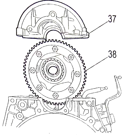
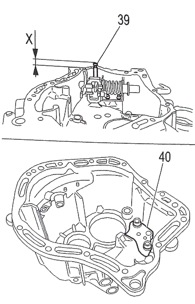
System composition:
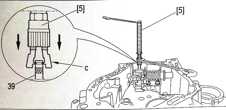
39 - locking finger;
40 - the locking pin support is secured with two screws in the gearbox housing.
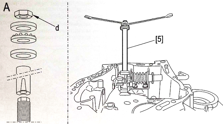
Attention. The seated pin (39) must protrude beyond the plane of the joint with the clutch housing by a distance of X = 8 + 0.5 mm. The use of device 5 guarantees this clearance.
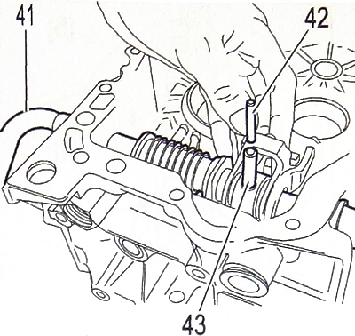
Note: Gearboxes that do not have a 5th gear/reverse gear inhibit system are equipped with a double locking pin (42) and (43) of the gearshift shaft (41).
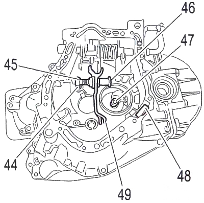
Remove:
- the rear gear fork (49) with its axle (46);
- locking finger (45);
- adjustment mechanism (44);
- magnetic strip (48);
- secondary shaft sleeve (47).
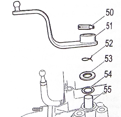
Press out the fastening pins (50) of the gear selector lever (51).
Remove:
- gear selector lever (51);
- adjustment mechanism (52);
- washer (53);
- seal (54);
- gear selection axis (55).
 |
 |