
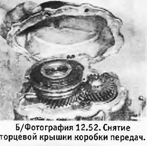
52. Remove the 8 bolts with washers securing the end cap. Remove cover (see photo).
53. Mark the relative position of the hub and the 5th gear synchronizer clutch.
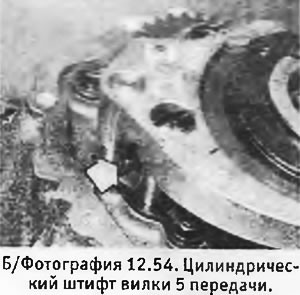
54. Engage 5th gear and knock out the 5mm roll pin securing the 5th gear fork to the stem (see photo).
55. While holding the 5th gear fork on the synchronizer sleeve, return the rod to the neutral position so that it comes out of the fork.
56. Engage any other gear to block the rods, and unscrew and remove the 28mm nut from the end of the input shaft. If the nut is locked, it must be unlocked.
57. Remove the hub and the 5th gear synchronizer clutch from the drive shaft together with the 5th gear fork. Be prepared for the detent ball to pop out of the fork.
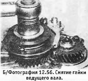
58. Reinstall the 5th gear synchronizer and engage 5th gear. Loosen the drive shaft nut and remove it. Remove 5th gear synchro again (see photo).
59. Remove the 5th gear gear, its bushing and spacer ring from the drive shaft.
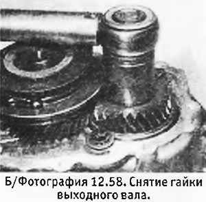
60. Remove the 2 bolts with washers securing the output shaft rear bearing.
61. Unclip the ends of the output shaft bearing circlip and remove the circlip. During assembly, it must be replaced, so do not be afraid to break it. If the ring is stuck in its groove, slightly raise the drive shaft.
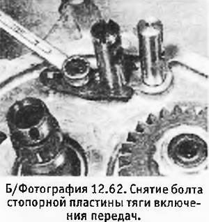
62. Unscrew the fixing bolt and remove the lock plate of the gear selection rod (see photo).
63. Remove the bolt securing the reverse idle gear shaft.
64. Remove the 13 bolts with washers securing the end cover to the main crankcase. Remove the end cap on the pins (you may need to hit the cover with a soft-faced hammer to release it. Never try to pry it off with any tool). Pay attention to the position of the clutch cable bracket.
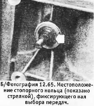
65. Remove the shift lever with spring from the shift shaft. Remove retaining ring and washer, press on shaft and remove O-ring (see photo).
66. Knock out the roll pin securing the shift pin and locking bracket to the gear shift shaft.
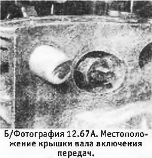
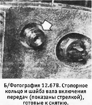
67. Inspect the cover protecting the gear shift shaft. If it is tapered, skip to the next paragraph. If it is cylindrical, remove it with pliers or an adjustable wrench and then press the shift shaft so that it moves towards the cover so that the retaining ring and washer can be removed from its end. These parts are not used on early models, where the shaft itself, the main case and the 3rd gear fork are of a slightly different design.
 |  |
68. Pull the gear shift shaft out of the box. Pull out of the box (as they are removed from the shaft) switch pin, locking bracket and spring with its Belleville washers. Pay attention to the position of the washers.
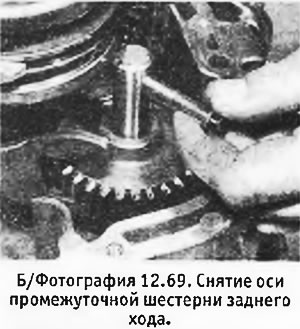
69. Screw the reverse idle gear axle bolt back into the axle and, using it as a lever, pull the axle out. Remove reverse gear (see photo).
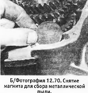
70. Remove the metal dust magnet from the crankcase (see photo).
71. Carefully pull out both sets of gears together with their shafts, as well as the forks and gear shift rods.
72. Remove the spring support bracket from the main crankcase.
73. If this has not already been done, knock the end cover of the gear shift shaft off the box using a beard with a diameter of not more than 14 mm.
74. Using a wire hook, pull the oil sprinkler out of the box.
75. Unscrew and remove the reverse light switch.
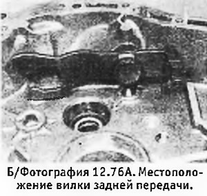
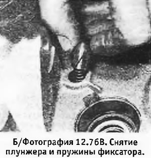
76. Remove the nut with washer securing the reverse fork stem. Remove stem and fork. Get the plunger and detent springs (see pictures).
 |  |
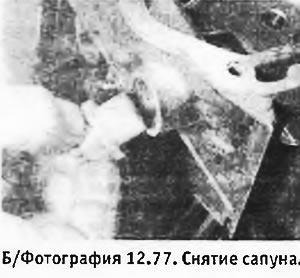
77. Unscrew the breather and remove it from the main crankcase (see photo). (On models with a reverse gear lock cable, there is a cable bracket in this place instead of the breather).
78. Going to the clutch housing, remove the release bearing (if it hasn't already been done). Remove the clutch release fork.
79. Unscrew the bolts and remove the release bearing guide tube.
80. Remove the shim located behind the tube that controls the axial movement and the outer race of the input shaft front bearing.
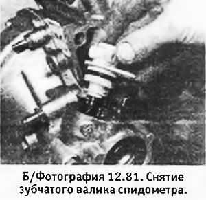
81. To remove the main gear, unscrew the bolts and remove the speedometer pinion and its adapter (see photo).
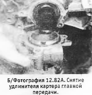
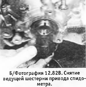
82. Remove the bolts and remove the extension. Remove the speedometer drive gear and bearing preload adjusting shim (see pictures). (Latest models do not have this gasket).
 |  |
83. Remove the bolts securing the final drive housing to the box. Remove the crankcase and final drive assembly. Pay attention to the position of the shift lever bracket.
84. Mark the outer races of the final drive bearings - if you are going to change them, they should be installed exactly in their original position during assembly.
85. Remove the shift lever from the main crankcase, which is fixed with a retaining ring and washer.
86. If you want to remove the clutch release lever ball joint, you will need a reverse hammer with a suitable grip. (On a new box, a ball joint may be missing).
87. Disassembly of the box is completed.