
- turn off the ignition and disconnect the wire «masses» from the storage battery;
- raise and secure the car, while hanging the front wheels;
- remove the front wheels;
- unscrew the nut fastening the pin of the ball joint of the tie rod end to the steering knuckle, while being careful not to damage the protective cover of the constant angular velocity joint of the drive shaft;
- using a puller, remove the ball joint from the steering knuckle;
- drain the fluid from the hydraulic circuit of the power steering;
Attention! To avoid contamination of the hydraulic circuit of the power steering, plug both openings of the control valve and both of its pipes with plastic plugs.
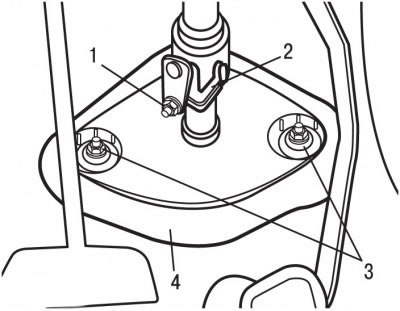
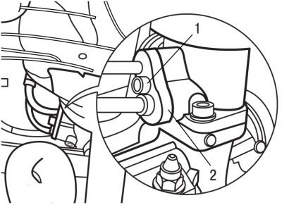
Pic. 7.7. Steering shaft lower mount: 1 - nut; 2 - latch; 3 - sealant; 4 - nut
- unscrew nut 1 (pic. 7.7) and remove the steering shaft, having previously removed the protective latch 2;
- unscrew nuts 4 and remove the seal 4 from the bulkhead of the engine compartment;
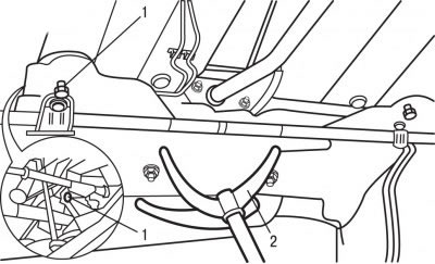
Pic. 7.8. The location of the bolts of the rear fastening of the sub-frame (1) and jack (2), supporting the subframe
- support the subframe with a jack 2 (pic. 7.8);
- unscrew the bolts 1 of the rear fastening of the sub-frame;
- on vehicles with DW10TD and DW10ATED engines, disconnect the exhaust system suspension cushions and the connecting element with the underframe;
Pic. 7.9. Bolt location (1) subframe support fastenings
- remove bolt 1 (pic. 7.9) fastening the support and lower the subframe by 60 mm;
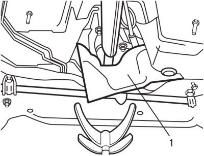
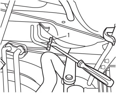
Pic. 7.10. Location of the heat shield (1)
- remove heat shield 1 (pic. 7.10);
- loosen the clamps and disconnect the hydraulic circuit hoses near the valve;
Pic. 7.11. Bolt location (1) fastening brackets
- remove bolt 1 (pic. 7.11) fastening brackets;
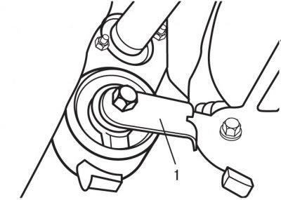
Pic. 7.12. Using a screwdriver to pry the bracket (1) valve
- use a screwdriver blade to move the bracket 1 (pic. 7.12) valve;
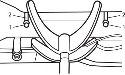
Pic. 7.13. Nut location (1) and hairpins (2) fastening the steering gear to the subframe
- unscrew nuts 1 and studs 2 (pic. 7.13) fastening the steering mechanism to the sub-frame;
- remove the toothed washers that are located between the steering gear and the sub-frame;
- remove the steering gear through the wheel arch on the driver's side.
To install steering gear:
- when installing, it is necessary to use new studs 2, self-locking nuts and rubber sealing rings of high and low pressure pipes;
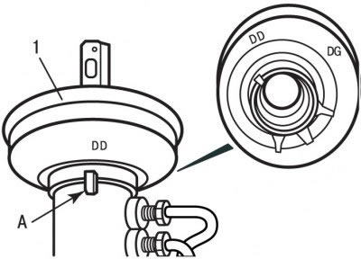
Pic. 7.14. When installing the seal, it is necessary to align the mark on the seal (1) with boss (A): DD - label for vehicles with right-hand drive; DG - label for cars with left steering wheel
- check the correct position of the seal 1 (pic. 7.14) on boss A in relation to the steering wheel side of the vehicle. For right-hand traffic, the DG mark must be aligned with boss A;
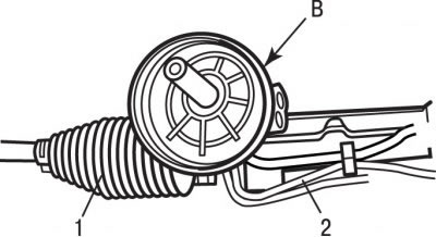
Pic. 7.15. Steering gear: 1 - protective cover; 2 - ventilation tube; B - bearing surface of the seal
- Apply a thin coat of LUBRICOMET SP70 to the bearing surface B (pic. 7.15) seal;
- check the reliability of fastening of the ventilation tube 1 with brackets and its connection with corrugated protective covers 2.
Installation is carried out in the reverse order of removal, taking into account the following:
- fill the working fluid into the hydraulic system of the power steering;
Attention! Tighten studs 2 (see fig. 7.13) torque 7.5 Nm. Tightening torque greater than 7.5 Nm will destroy the steering gear. Be sure to install toothed washers between the steering gear and the subframe.
- to top up and fill the system, use only fresh working fluid;
- adjust wheel alignment.