
Transfer case elements
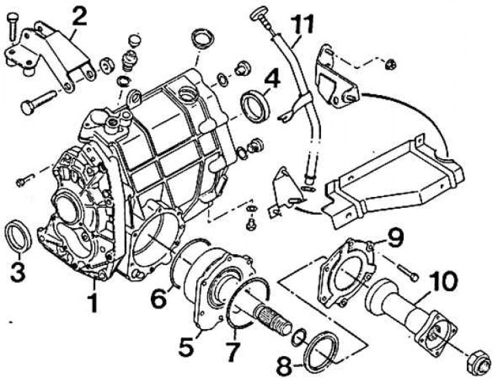
1 - transfer case; 2 - top bracket; 3 - sealing ring; 4 – a sealing ring of a forward right semiaxle; 5 - intermediate rear bearing; 6; 7 - round sealing ring; 8 – a sealing ring of a back exit of a drive; 9 - closing plate; 10 - drive rear connector; 11 - oil level indicator
The transfer box is located in the axis of the front drive shafts, behind the engine. It provides distribution and control of the drive torque to the rear wheels through a planetary center differential. This design solution produces a torque split in the following proportion: 53% to the front wheels and 47% to the rear. The front drive axle with a classic differential splits the torque between the two front wheels. Thanks to the electromagnetic interlock, a rigid connection of the intermediate planetary gear is made.
Box type: TK2A.
Removing the transfer case
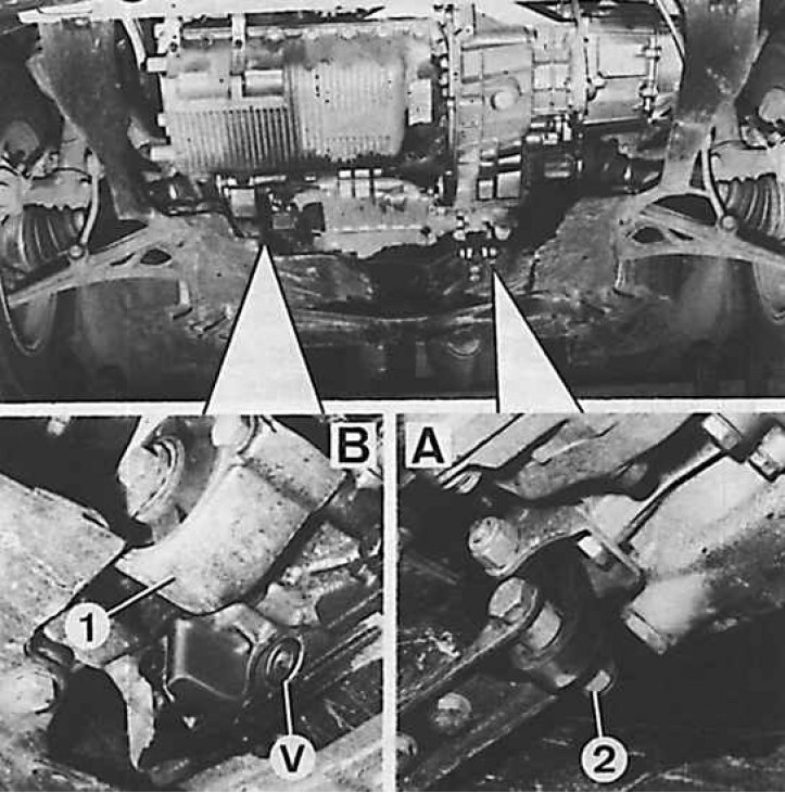
Pic. B: V - drain plug, 1 - engine rear bracket
Pic. A: 2 - flange of the travel limiter
The transfer box is removed from the bottom of the car.
Removing
1. Drain the oil from the transfer case and the liquid from the cooling system.
2. Remove drive shafts.
3. Remove the upper fastening element of the transfer case oil level gauge guide. Remove the oil level guide from the transfer case.
4. Unscrew the bolts securing the stabilizer bearing and the bolts securing the steering gear housing to the front crossmember.
5. Remove the engine bottom bracket connection clamp.
6. Remove the bolts securing the center differential lock motor.
7. Remove travel limiter shaft.
8. Unscrew the bolts securing the engine cross member, having previously installed the telescopic stand at the bottom.
9. Remove cross member (it needs to be done together).
10. Remove the travel limiter and its clip.
11. Install the steel rod so that the front of the drive shaft does not fall out, and then unscrew the bolts that secure the front flange to the drive output connector.
12. Remove drive shaft (do not separate the front part of the shaft from the intermediate bearing, because it causes loss of balance).
13. Neutralize the action of the automatic lock cable tensioner by turning it a quarter of a turn.
14. Remove the differential lock motor control cable.
15. Remove transmission control.
16. Remove the water inlet housing to the cylinder block.
17. Disconnect the speedometer cable from the transfer case.
18. Install a telescopic stand under the transfer box (place a wooden block).
19. Remove the upper transfer case mounting element.
20. Disconnect the differential lock indicator light connector.
21. Remove the right bracket of the transfer case and unscrew the bolts of its fastening to the gearbox.
22. Remove the transfer box on the right side.
Installation
1. Installation consists in performing the steps in reverse order with respect to the removal process. Care should be taken to install the transfer case with new o-rings, lubricate the left drive shaft bearing with Molykote BR2 Plus, install new self-locking nuts, lubricate the rear drive shaft bolts with Loctite, and tighten all bolt connections to the appropriate torque.
2. Fill with oil, coolant and bleed air from the cooling system, following the recommendations for the use of operating fluids (see subsection 2.1).
Transfer case repair
Only seals and o-rings should be replaced, as they are the only ones available as spare parts.