
Mounting the selector shaft
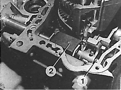
1 - axis
2 - remote element
1. Replace the input shaft tapered bearing outer race. For removal use tool 8.0317 A and for installation use tools 8.0317 A and E.
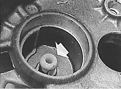
2. Check the condition of the plastic element (indicated by an arrow) oil supply to the secondary shaft, and then install the selector pin.
3. Install the differential in the outer housing, lubricate the surfaces of the cover with "Loctite Formetanch". Fasten the cover.
4. Install O-ring (tool 8.0317 G).
5. Measure differential bearing preload (if necessary). Install gasket 8.0317 L (2.2 mm thick), and then the bearing housing without the speedometer drive driver and without the O-ring. Gradually tighten the bolts to the required torque, turning the differential all the time, and then unscrew and remove the bearing housing.
6. Remove gasket 8.0317 L and measure the distance between the outer bearing ring and the connection surface of the outer differential housing (depth gauge should be used).
7. Measure the seat height of the bearing housing.
8. Find the difference between both measured values. To find the thickness of the gasket that should be installed in order to provide the necessary preload of the bearings, it is necessary to add 0.1 mm to the found value.
9. Install the speedometer drive assembly on the bearing housing, insert the O-ring and secure the bearing housing to the outer differential housing. Tighten the bolts to the required torque.
10. Install the O-ring in the bearing housing.
11. Install the release bearing guide and bearing outer race.
12. Install reverse frame (if it was removed).
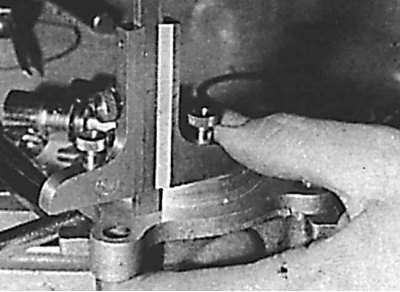
13. Prepare the selector shaft: using tool 0317 C, compress the spring together with its two plastic cups, align the selector pin and the locking clip (tube with a diameter of 13 mm and a length of 34.5 mm).
14. Insert the selector shaft, remove the spring compressor, install the pins.
15. Install the intermediate connector for the selector shaft lever, the O-ring, the rest of the components, as well as the connector, gasket and nut.
16. Install special selector shaft seal (attachment 8.0317 B), and then the axle cap.
17. Place the magnetized plate in the crankcase and install the crankcase. Lubricate the surface with "Loctite Formetanch".
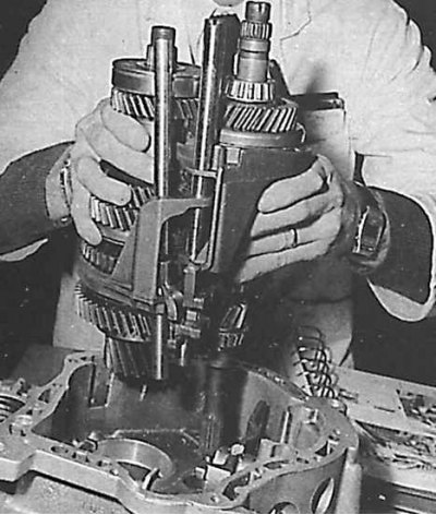
18. Fold the primary and secondary shafts with forks and their axles and install everything together in the crankcase.
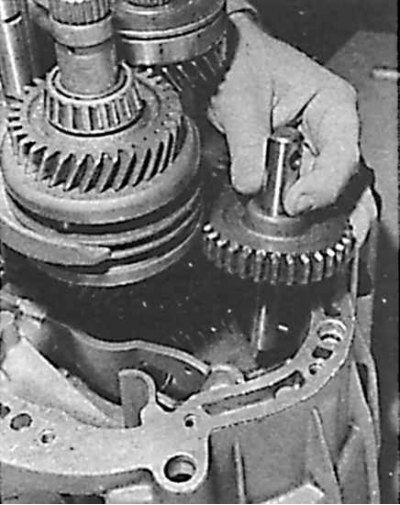
19. Install the reverse shaft and gear. Position the axle pin appropriately and make sure that the bevel of the gear teeth is pointing up (to facilitate the installation of the gear, the reverse gear frame should be raised).
Attention! Screw in the bolt of the reverse gear axle (tightening torque - 20 Nm).
20. Install the fixed axle latch, output shaft bearing snap ring. Raise the entire assembly to facilitate its installation. Tighten the two bearing bolts to 15 Nm.
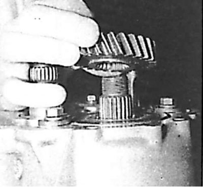
21. Install the 5th gear of the output shaft; The flange must be on the bearing side.
22. Install the thrust washer of the outer bearing race of the clutch shaft. Pay attention to correct installation.
23. Install the 5th gear bushing and then the 5th gear and sliding sleeve together with the hub.
24. Engage two gears, tighten the output shaft nut (50 Nm) and secure it from unscrewing.
25. Remove the 5th gear displacement bushing, insert the forks, and then secure it all with a ball and locking spring.
26. Engage two gears again and tighten the input shaft nut (50 Nm), and then secure it from unscrewing.
27. Disengage 5th gear and then secure the pin.
28. Lubricate with "Loctite Formetanch" and install the 5th gear assembly cover.