



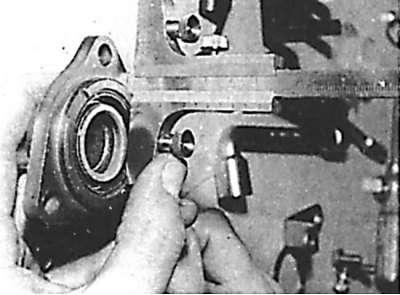
Measuring the primary shaft bearing interference - measuring the release bearing guide flange
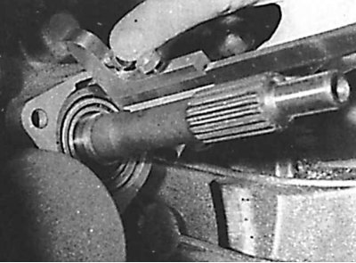
Measuring the primary shaft bearing interference - measuring the distance between the outer ring of the bearing and the crankcase joint surface
Gear shift mechanism
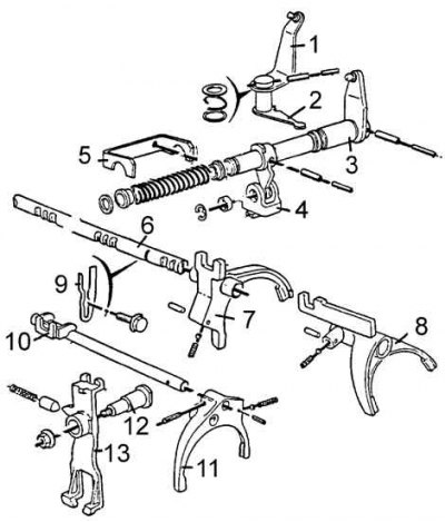
1 – gear shift lever rod, 2 – reverse gear lock bushing, 3 – reverse gear lock cable, 4 – gear selector rod, 5 – intermediate element, 6 – gear selector connector, 7 – gear selector lever, 8 – intermediate gear shift lever, 9 – intermediate connector of external gear shift mechanism, 10 – selector shaft lever, 11 – bracket, 12 – selector shaft and pin, 13 – key
Internal gear shift mechanism (gearbox BE 3)
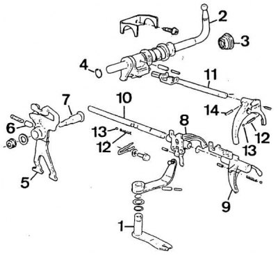
1 – selector lever, 2 – selector shaft, 3 – sealing ring, 4 – mounting ring, 5 – intermediate reverse gear lever, 6 – cotter pin, 7 – shaft, 8 – forks of gears 1–2, 9 – forks of gears 3–4, 10 – shaft of forks of gears 1–2 and 3–4, 11 – shaft of forks of gear 5, 12 – spring, 13 – locking ball, 14 – pin
1. Remove the release bearing guide bush. If signs of wear are found, it should be replaced.
2. Install a 2.4 mm thick 8.0317 K gasket behind the release bearing guide sleeve. Secure the guide sleeve, observing the required tightening torques.
Original is located at PeugeotBook.ru
3. Use a depth gauge to measure the bearing fit relative to the housing surface, as well as the flange of the release bearing guide sleeve without its seal. To determine the bearing tension, calculate the difference and add 0.03 mm to the resulting value (paper seal thickness).
4. Replace the release bearing guide bush seal ring (shank 8.0317 H).
5. Install the gasket of the calculated thickness, seal and guide bush. Tighten the three bolts to 12.5 Nm.
6. Secure the clutch release rod, release bearing and, to prevent movement that could make it difficult to install the transmission, secure the rod to the crankcase.