
Transmission housing assembly
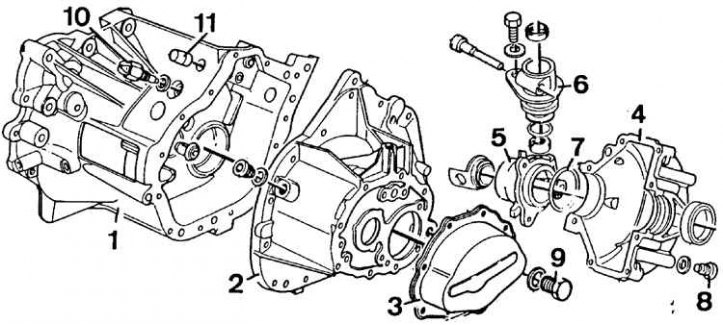
1 - clutch housing, 2 - gearbox housing, 3 - rear cover (5th gear housing), 4 - outer housing of the differential, 5 - bearing housing, extension of the differential, 6 - housing of the speedometer drive unit, 7 - sealing ring, 8 - oil drain bolt, 9 - filling and oil level control bolt, 10 - reversing light switch, 11 – deaerator
Removing
1. Raise the hood and place it in a vertical position.
2. Remove battery and bracket.
3. Remove the air filter assembly.
4. If equipped, remove the power steering pump without disconnecting the hoses. Remove the power steering pump mount.
5. Disconnect from gearbox:
- clutch cable;
- braided ground wire;
- reversing light switch wires.
6. Remove starter.
7. On early models of cars, disconnect the reverse gear lock cable from the gearbox by unscrewing the plastic nut and removing the plunger.
8. On XU10J4 models (with 16 valves), unscrew the bolts securing the throttle body and the power steering tube suspension. Also unscrew the suspension mounting strut from the gearbox.
9. Raise and place the front of the vehicle on stands.
10. Remove mudguard from engine.
11. Remove front wheels and plastic transmission cover.
12. Remove the anti-roll bar link bolts from the lower front suspension arms.
13. Using a special ball joint puller, remove the lower ball joints from the steering knuckles.
14. On XU10J4 models (with 16 valves) support the lower frame on a jack, then unscrew the lower frame mounting bolts and steering gear bolts. Lower the lower frame and remove it from under the vehicle.
15. Drain the oil from the gearbox by unscrewing the bolt located at the bottom of the outer case of the differential.
16. Unscrew the central mounting bolt from the rear suspension of the power unit. Loosen the nuts securing the intermediate bearing housing and turn the bolts half a turn to release the eccentric heads and separate the right drive shaft from the gearbox.
17. Using a screwdriver, remove the linkages from the shift lever ball joints.
18. Detach left drive shaft from gearbox.
19. Disconnect:
- intake exhaust pipe from the manifold;
- TDC sensor from the engine block.
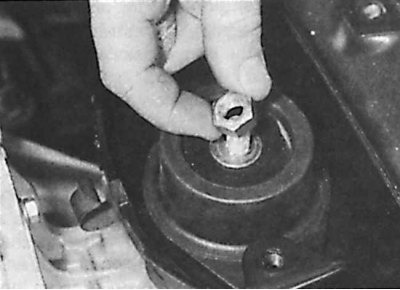
20. Unscrew the bolt and remove the speedometer drive together with the O-ring.
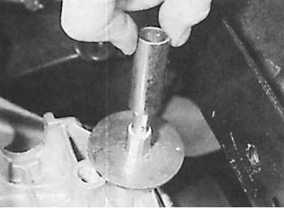
21. Unscrew the bolts and remove the speedometer drive housing.
22. Remove the speedometer drive gear and shims.
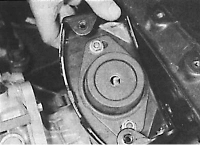
23. Remove the bracket connecting the gearbox to the body.
24. Hook the winch to the engine and raise it just enough so that the weight of the engine and gearbox can be supported by the winch.
25. Unscrew the nut from the left front suspension, then unscrew the bolt from the suspension to the body.
26. In the place where the suspension is welded to the body, unscrew and remove the rubber cushion.
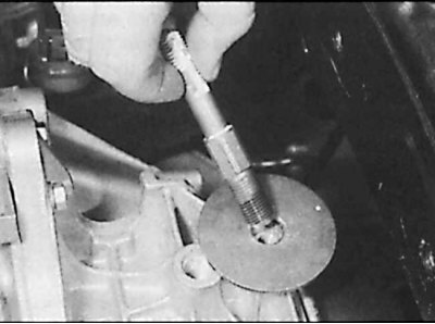
27. Remove protective tube (in the presence of) from the installation rack, then unscrew the rack from the top of the gearbox housing.
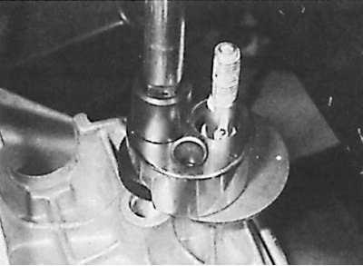
28. If the stand cannot be unscrewed, a universal tool for unscrewing the threaded studs must be used.
 | 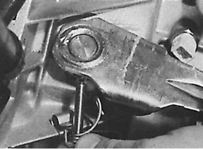 |
29. On XU10J4 models (with 16 valves) with ball head clutch release mechanism remove pin (drawing on the left) or unscrew the bolt and remove the clutch release lever from the top of the clutch release shaft (drawing on the right).
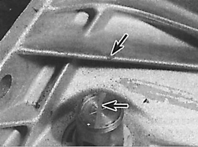
30. Apply alignment marks (indicated by arrows) in the center of the upper part of the clutch release shaft and on the gearbox housing. Unscrew the bolts and remove the clutch cable hanger from the top of the gearbox housing.
31. Lower the engine as far as possible without damaging the right engine mount.
32. Support the gearbox on a jack.
33. Unscrew the bolts securing the gearbox to the engine.
34. Move the jack and gearbox to the left, remove from the guide pins and rotate the differential up to disengage the gearbox from the lower frame.
35. Lower the gearbox and remove it from under the vehicle.
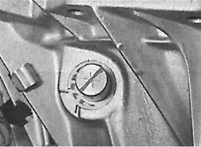
36. On models with a ball-tip clutch release, apply a second alignment mark on the gearbox housing, noting the relative position of the release fork mark after removal, and note the angle that the release fork has rotated. This mark is used to position the release fork before reinstalling it to properly engage the release bearing.
Installation
1. Installation is carried out in the reverse order of removal, taking into account the following points.
2. Lubricate input shaft splines, release bearing guide bushing, clutch release lever lugs, clutch release lever ball joint with a light coat of Molykote BFF2 plus grease.
3. Check that the guide pins are in place before installing the gearbox.
4. On models with a ball head clutch release, install the clutch release bearing with the mark up and align the mark on the fork shaft with the second mark made on the transaxle case.
5. Apply anti-screwing agent to the threads before screwing in the column.
6. Replace drive shaft seals and install drive shafts.
7. Pour oil into the gearbox.
8. Replace self-locking nuts.