



Table of contents: Examination 🠇 Adjustment 🠇
Calculating the thickness of the valve adjusting shim
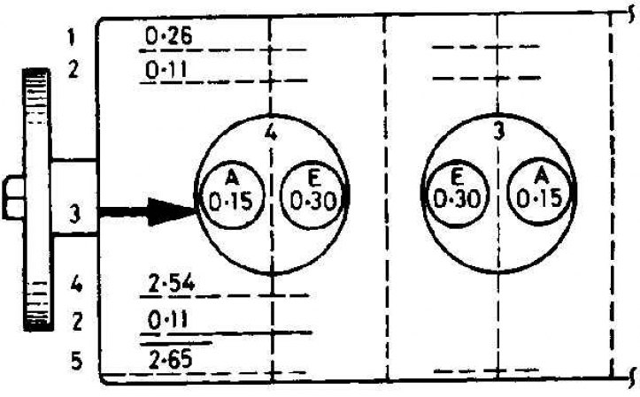
A. Inlet valve; E. Exhaust valve
1. Measured gap; 2. Difference between 1 and 3; 3. Normal clearance; 4. Thickness of the installed adjusting shim; 5. Calculated thickness of the new adjusting shim
Examination
1. Checking the valve adjustment should be done after valve knocking, major engine repairs, or when engine power decreases. Check and adjust on a cold engine.
2. Apply the handbrake, raise the front of the car and remove the right front wheel.
3. Remove the plastic fender guard to access the crankshaft pulley mounting bolt.
4. Turn the crankshaft using the pulley mounting bolt until the holes in the pulley and cylinder block are aligned and lock the pulley with the installation rod. To make it easier to turn the crankshaft, unscrew the fuel injectors.
5. Remove the cylinder head cover.
6. Draw a diagram of the engine and number the cylinders from 1 to 4. Cylinder 1 is on the gearbox side. On each cylinder, draw the inlet and outlet valves. Above each cylinder in the drawing, draw two horizontal lines. On line #1, write down the actual clearance of all valves, and on line #2, the amount by which the clearance must be changed to obtain the required clearance.
7. Turn the crankshaft until the intake valve of cylinder 1 is completely closed, i.e. the camshaft cam on this valve should point upward.
8. Using a feeler gauge, measure the clearance between the base of the cam and the tappet. Record the actual clearance on line #1 opposite the appropriate valve.
9. Repeat the measurement for the remaining seven valves, rotating the crankshaft as necessary so that the cam lobe of the valve being tested points upward.
10. Calculate the difference between the actual and required clearance and write it down on line #2.
11. If all clearances are within the required limits, install the cylinder head cover, install the plastic cover under the fender, install the wheel and lower the car. If the actual clearance is not within the specified limits, adjustment must be made.
Adjustment
1. Remove the camshaft.
2. Remove the first tappet from the head and remove the shim from the top of the valve. Clean the shim thoroughly and measure its thickness with a micrometer. The shims are usually marked, but their thickness can decrease due to wear.
3. Referring to the valve clearance measurements, it is necessary to determine the thickness of the new adjusting shim. If the actual valve clearance was greater than required, the thickness of the adjusting shim should be increased by the value recorded on line No.2 opposite the corresponding valve. If the actual valve clearance was less than required, the thickness of the adjusting shim should be reduced by the value recorded on line No.2 opposite the corresponding valve.
4. In the diagram, draw three horizontal lines below each valve. On line #4, record the measured shim thickness, then add or subtract the value recorded on line #2. The result is the shim thickness that must be installed to obtain the optimum valve clearance. This should be recorded on line #5.
5. Repeat the operation to select a new adjusting plate for the remaining valves.
6. When installing a new gasket, install it with the marking facing down. Install the pushers on top of the adjusting gasket.
7. Install the camshaft and re-measure the valve clearance.