
Replacement of brake pads
On the back side of the support shield of the brake mechanism there is an inspection hole plugged with a plug. After pulling out the plug, you can shine a flashlight into the hole and visually check the thickness of the brake linings. Removing the brake pads is performed as follows.
1. Loosen the wheel bolts and place the rear of the vehicle on jack stands.
2. Remove rear wheels.
3. Knock off the protective cap of the hub nut with a chisel. The cap is knocked off along the entire diameter of the fit to the hub. The hub must be rotated.
4. Turn out a bolt of fastening of a brake drum and remove a drum. If it does not come off, then the drum can be knocked down with a plastic or rubber mallet by striking around the circumference of the drum. If it is not possible to knock down the drum in this way, then you can insert a punch of a suitable diameter (or screwdriver) hole as shown in (illustrations 3.4), on the back of the brake drum. The punch will hit the parking brake lever and release the lever. The brake pads will then be in the neutral position.
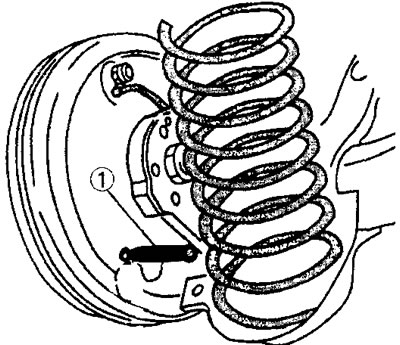
3.4 Insert a punch of suitable diameter into the hole on the back of the brake drum to depress the parking brake lever and move the brake pads to the neutral position
5. Remove the brake drum from the hub, while feeding it from side to side (see illustration).
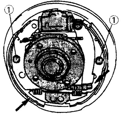
3.5 Brake drum assembly. In order to disassemble the brake mechanism, it is necessary to remove the pins 1 of the brake pads. At the point marked with an arrow on the right side, there is a parking brake lever, on which the parking brake cable is attached. The arrow on the left side indicates the return spring mounting
6. Disconnect the upper return spring using pliers.
7. Remove the pins 1 fastening both brake pads (see illustration 3.5). Hold the pin itself with your finger on the back side of the support shield and at the same time turn the pliers on the end side of the pin and release the clamp of the guide spring, which is on the pin.
8. Remove clip and spring. Feed the pin to the back side and remove it. Follow the same steps with the pin of the other brake pad.
9. Clamp the end of the parking brake cable with pliers (see arrow in illustration 3.5) and pull it outward to compress the spring and allow the cable to be released from the parking brake lever.
10. Remove both brake pads from the support plate by pushing them towards you. After that, close the lower ends of the blocks (see arrows in illustration), so that the upper part of the shoes comes out of the wheel cylinder, and so that the parking brake lever expander bar is released along with the adjusting mechanism.
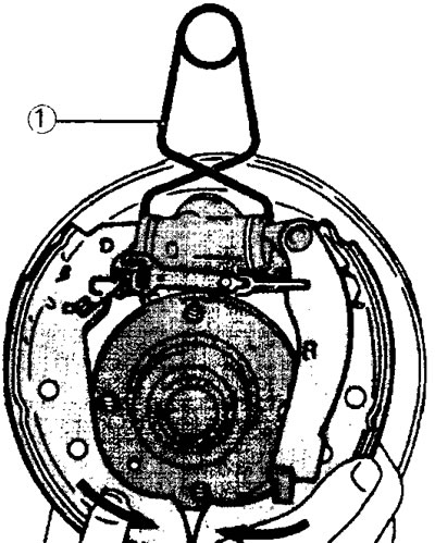
3.10 Remove both brake pads from the base plate by pushing them towards you. After that, close the lower ends of the blocks. Spring 1 is designed to hold the pistons of the wheel cylinder inside the cylinder. To prevent the pistons from leaving the cylinder, it can be covered with an elastic band
11. Note the mounting position of the adjustment mechanism. The regulator gear must be installed in the same position, because both ends of the adjustment mechanism are not equal. When the shoes are removed, the lower return spring and the small expander bar return spring will be released and can also be removed.
Attention! Be careful not to damage the protective cap of the wheel cylinder when removing the brake pads. To prevent the pistons from leaving the cylinder, it can be covered with an elastic band or elastic band. Note the mounting position of the drum brake parts to facilitate subsequent assembly.
12. Make sure that the parking brake levers on the brake shoes move easily. It is possible that new brake pads may be supplied without levers. In this case, rearrange the levers from the old brake pads (see illustration).
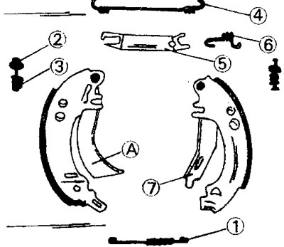
3.12 Details of the brake mechanism of back wheels. The letter A indicates the shoulder on the parking brake lever, which locks the lever. When the lever is pressed with a punch inserted from the rear side of the brake shield, this collar disengages and the lever is released.
1 - lower coupling spring
2 - clamp the guide spring on the shoe pin
3 - shoe fastening pin and guide spring
4 - upper coupling spring
5 - expanding bar
6 - return spring of the expansion bar
7 - parking brake lever
13. Clean all parts of the rear wheel brake mechanism, including the shield. If washing gasoline is used for cleaning, do not allow it to get on the rubber caps of the wheel brake cylinder.
If the brake pads have a residual thickness of 1.0 mm, the brake pads must be replaced. It is also recommended to change the brake pads if the lining thickness is 2.0 mm. If there are signs of brake fluid leakage from the wheel cylinder, the cylinder should also be replaced. The wheel cylinder cannot be repaired.
Attention! Do not clean the brake mechanism with compressed air. With this method of cleaning, the dust generated during the friction of the brake linings enters the respiratory tract. This dust is harmful to health.
Installation
If the wheel cylinder was removed, then it should be installed in place.
14. Lubricate the contact points of the brake pads on the brake shield. There are six such points. Apply lubricant to these areas with your finger.
15. Replace the lower part of the brake shoes and secure the lower return spring to the shoes.
16. Insert the expansion bar into the slot on the top of the brake shoe and secure the spring to it.
17. Attach the top of the rear brake shoe to the shield.
18. Fasten the expander bar return spring to the block.
19. Pull the brake shoe towards you so that both springs are stretched, and the top of the brake shoe enters the hole in the wheel cylinder.
Attention! Be careful not to damage the protective cap of the wheel cylinder.
20. Attach the parking brake cable to the rear brake shoe lever. Release the cable spring and make sure that the parking brake cable is well secured on the drive lever.
21. Center the brake pads on the shield.
22. Insert from the back side of a board of the brake mechanism pins of fastening of pads and put on pins directing springs and clips. While holding the pin on the back of the brake shield, grab the spring guide clamp with pliers and push it onto the pin head. Once the pin head has passed through the hole in the clip, turn the clip to lock it onto the pin. Re-center the brake pads on the brake shield.
To set the brake pads to the basic position, it is necessary to rotate the adjusting gear on the expansion bar until both pads are in such a way that the diameter of the circle they form is 225 mm (X value) (see illustration 3.22). Measure the diameter of the brake drum at the same time. If a reworked brake drum is installed, the maximum allowable drum diameter must be no more than 256 mm.
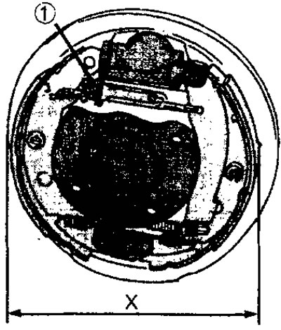
3.22 Measuring the diameter of the circle formed by the installed brake pads (X value). The position of the brake pads is adjusted using the setting gear 1 of the adjusting mechanism
23. Install the brake drum and secure it with a bolt, which is tightened to a torque of 25 Nm.
24. Apply the parking brake and depress the brake pedal several times to activate the self-adjusting brake mechanism and center the brake shoes in the drum. The parking brake sometimes needs to be adjusted.
25. Take a test drive. Take some care so that the brakes run in.
The rear drum brake wheel cylinder can be removed after removing the brake pads. Considering that the cylinder is not disassembled, it should be replaced as a set in case of suspicion that it is faulty or has a defect. When installing the wheel cylinder, the bolts of its fastening are tightened with a torque of 14 Nm.