



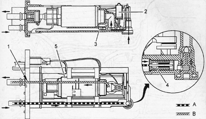
6.0. Pump for injecting additives that prevent carbon formation into fuel A - additive return circuit; B - low pressure circuit; 1 - non-return one-way valve in the low pressure circuit; 2 - additive level sensor in the tank; 3 - filter; 4 - one-way valve in the return circuit; 5 - additive injection pump
The pump delivers 80 liters per hour, and the additive delivery pressure is 3 bar. The additive delivery is controlled by the engine control unit, which is connected to the pump via a six-pin connector. Purpose of the plug contacts:
- 1 - terminal (-) of the additive level sensor in the tank;
- 2 - terminal (+) of the additive level sensor in the tank;
- 3 - 12V pump power supply;
- 4- "mass" (-) of the pump;
- 5 - not used;
- 6 - not used.
When the additive level in the tank is 0.3 liters, the level sensor is triggered and a corresponding message is displayed on the instrument panel or the corresponding signal lamp lights up.
The additive tank has a safety valve that provides ventilation of the tank and prevents liquid from leaking out (see illustration 6.0a).
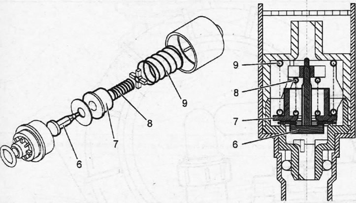
6.0a. Safety valve of the additive fluid tank 6 - spool. Activated by low pressure of 0.036 bar; 7 - pressure reducing valve (0.05±0.01 bar); 8 - spool return spring; 9 - return spring of the pressure reducing valve
The relief valve is located in the rear left wheel arch under the fender liner (see illustration 6.0b).
(Original is contained on the portal: www.PeugeotBook.ru)

6.0b. Location of the additive tank relief valve