



Depending on the engine type, different types of injectors are installed. Figure 366 shows a section of the injector. The injector marking is applied to its holder. On naturally aspirated diesel engines, the injectors have an orange mark, while on turbodiesel engines, the injectors are marked with a white mark. The color mark is applied at location (A) in Figure 366.
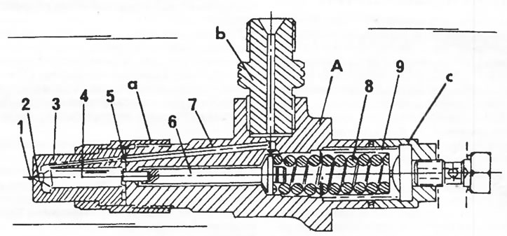
Figure 366. Nozzle in section. At location (A) the marking is applied. 1. Injection hole; 2. Jet seat; 3. Nozzle body; 4. Injector needle; 5. Contact surface of the injector; 6. Pusher; 7. Nozzle holder; 8. Spring; 9. Adjusting screw; 10. Tightening torques: a = 85 nm, b = 65 nm, c = 20 nm
To identify a faulty injector, you should disconnect the injection tubes one by one and start the engine. If removing a specific injection pipe does not change the engine operation, the corresponding injector is not working.
The injectors are not screwed into the cylinder head in the usual way, but are inserted and ignited by jumpers. Each jumper is secured with a spacer and a contact washer.
The injector is removed as follows:
- Unscrew the injection pipe. The most convenient way to loosen the union nut is with a slotted open-end wrench. Disconnect the fuel return hose from the injector.
- Unscrew the jumper nuts, remove the washers and the jumper. When removing the injector, the copper washer (1) and washer (2) in Figure 367 are replaced.
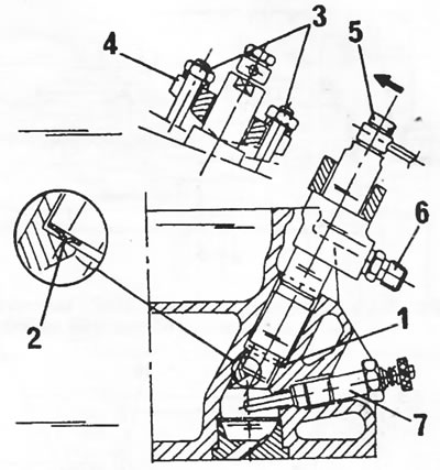
Figure 367. Sectional view of installed injector. Copper washer; Convex washer; Nuts, 25 nm; Jumper; Union nut, 25 Nm; Hollow bolt, 9 Nm; Glow plug, 28 nm
- Insert a new washer (2) with the convex side facing up. The washer should be lubricated with a general purpose grease. Also apply a lubricated copper washer and insert the nozzle.
- Install the jumper, apply both washers, and tighten the nuts evenly to a torque of 25 Nm. Dimensions "a" and "b" in Figure 368 must be the same on both sides.
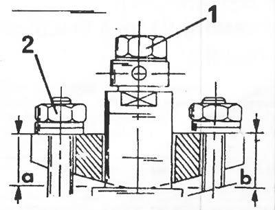
Figure 368. When tightening the injector jumper, dimensions "a" and "b" on both sides must be the same. 1. Contact, 9 nm; 2. Nuts, 25 nm