



Table of contents: Thermal switches and temperature…🠇 Antifreeze - general information 🠇 Water hose clamps (405 models with…🠇 Water hose clamps (205 models from…🠇 Thermostat (latest models) — general…🠇 Fan thermal switches (latest models)…🠇 Coolant loss through fuel filter…🠇
1. Disconnect the negative cable from the battery.
2. Remove the radiator grille.
3. Disconnect the wiring at the electrical connector.
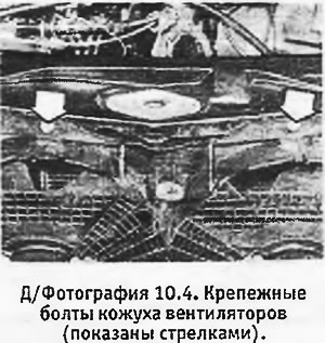
4. Loosen the mounting bolts and remove the fan shroud (fans) (see photo).
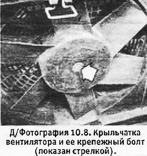
5. If necessary, unscrew the nuts and remove the fan motor from the casing (fan electric motors). You can unscrew the bolts and remove the impeller (impellers) from the electric motor shaft (electric motor rollers) (see photo).
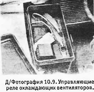
6. Installation of fans is carried out in reverse order. If the fans start to work poorly, you should check their relays, which are located on the left side of the engine compartment (see photo).
Thermal switches and temperature sensors (all models) - compaction
1. Depending on the model and equipment of the machine, various thermal switches and temperature sensors may be located on the thermostat housing.
2. When installing a new thermal switch or sensor, it is necessary to cover its threads with a suitable sealant (Loctite Fornseal or similar) to prevent coolant leakage.
Antifreeze - general information
1. Over a certain period of time (until the end of 1992.) the manufacturer recommended different concentrations of antifreeze depending on whether the engine was turbocharged or not (see Specifications). Currently, a mixture containing 50% antifreeze is recommended for all engines, which provides protection against freezing down to -35°C.
Water hose clamps (405 models with turbo engine) — general part
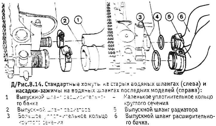
1. Since mid-1991, on 405 models with a turbo engine, the hoses are attached to the radiator and expansion tank without the use of clamps. Instead, the ends of the hoses have special clamping attachments equipped with sealing rings.
2. To disconnect the hose with a new type of clamp, turn the clamp counterclockwise and pull it out of the branch pipe on the engine, radiator or expansion tank.
3. Before installing the hose, check the nozzles for deformation and broken fasteners. If at least one of the nozzles is damaged or deformed, the hose must be replaced, since the nozzle cannot be replaced individually. If the O-rings are damaged or deformed, they should be replaced.
4. Before inserting the hose nozzle into the pipe, apply a small amount of sealant to the sealing ring, then insert the hose and turn the nozzle clockwise to lock it.
Water hose clamps (205 models from late 1992.) — general information
1. During a certain period of Burden (since the end of 1992.) some models with the XU07 engine used a new type of radiator hose clamp. The new type of clamp is shown in Figure 8.15.
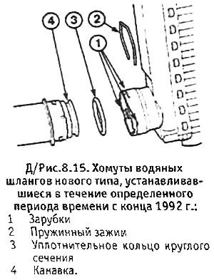
2. To disconnect the hose, you must first remove the spring clamp (you can use snap ring pliers for this purpose).
3. Disconnect the hose from the radiator pipe and remove the O-ring.
4. Before installing the hose, you should first insert the spring clamp into the notches. To do this, you first need to partially install the clamp into one of the notches, and then gradually insert it into the remaining notches.
5. Dip the sealing ring into the coolant and place it in the groove at the end of the hose. A ring soaked in coolant will be easier to install - other types of lubricant cannot be used.
6. Bring the hose to the radiator outlet, correctly aligning the three retaining tabs, and insert the hose into the outlet until it snaps into place.
7. Gently pull on the hose to check that it is securely in place.
Thermostat (latest models) — general information
1. Since the end of 1992, all engines have been equipped with an 83°C thermostat.
2. The new thermostat can be identified by the colored dot on the main body. On all models except the 309 with the XUD7T engine, this dot is green; on the 309 model with the XUD7T engine, it is white.
Fan thermal switches (latest models) — general information
1. Since the end of 1992, thermal switches and coolant temperature sensors have been standardized on all engines. The operating temperatures of the thermal switches are specified in the Specifications.
2. On models without air conditioning, the thermal switches have a pinkish-purple stripe on the housing instead of red.
3. On models with air conditioning, the coolant temperature sensors have a white connecting bracket.
Coolant loss through fuel filter heater hose
1. On models without a modified fuel filter, the filter heater hose may chafe against the timing belt cover, resulting in coolant leakage. To prevent this from happening, you should check that the hose is correctly positioned in its clamp and that the filter housing is positioned so that the hose does not touch the timing belt cover.