



- Check the absence of twisting and bending of the connecting rods on a connecting rod testing machine. It is best to have this done in a workshop, as bent or even twisted connecting rods can interfere with the normal operation of the engine.
- Lubricate all parts with engine oil.
- Position the pistons and connecting rods for assembly, i.e. the cutout in the combustion chamber and the protrusion for the connecting rod bearing shell should be located on the same side, as shown in Figure 272.
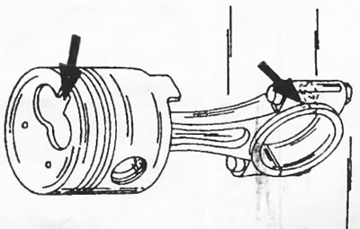
Figure 272. Correct assembly of piston and connecting rod.
- Insert the piston pin into the piston in the manner described above and align the connecting rod hole and the piston hole.
- Secure the piston with a retaining ring. Check the installation of the retaining ring around the entire circumference.
- Insert the piston pin from the other side of the piston, pass it through the connecting rod hole and press it until it stops. If necessary, use a plastic hammer. After this, install the second piston retaining ring.
- Holding the piston in your hands, move the connecting rod in different directions. The connecting rod should move easily.
- Install piston rings on the pistons. In this case, in accordance with drawing 270 take into account that:
*The factory marking of the piston rings or the inscription "TOP" must be located on top.
- The joint of the oil scraper piston ring must be located in line with the hole for the piston pin. The joints of the other two rings should be located at an angle of 120° from the joint of the oil scraper ring. The location of the piston ring joints is shown in figure 270. Before continuing work, compare the assembled piston with the drawing. Generously lubricate the piston rings with engine oil.
- Lubricate the piston with engine oil and insert it into the corresponding cylinder bore. To compress the piston rings when installing the piston, appropriate compression bands are required. Place the tension band around the piston so that the top edge of the piston protrudes by another 4-5 mm (Figure 273). This ensures that the piston is inserted into the cylinder bore.
- Install the connecting rod bearing caps according to the instructions section 16.2.
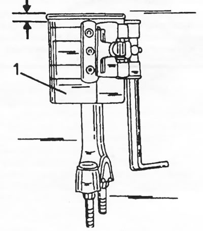
Figure 273. Applying the tension band to the piston. The piston should protrude by 4-5 mm.
(Material copied from the resource PEUGEOTBOOK)