
English Русский
Български
Беларускі
Український
Српски
Hrvatski
Română
Polski
Slovenský
Magyar
Bookmark Articles Sitemap Contacts
Company Hyundai Company Opel Company Skoda Company Kia Company Mitsubishi Company LADA Company Audi
PeugeotBook.ru


Series 100   Series 200   Series 300   400-500   Series 600   Crossovers   Others
 
Partner I (1996-2008) Peugeot 807 (2002-2014) Peugeot 806 (1994-2002) Peugeot J5 (1981-1993)

Installing the cylinder head (Peugeot J5)

  • Main
  • Пежо
  • Peugeot J5 (1981-1993)
  • Diesel engine
  • Engine repair (DB9)
  • Installing the cylinder head
0
Thoroughly clean the threaded holes for the cylinder head bolts. The holes must be dry and free of grease. If necessary, tap the thread with an M12x150 tap. Then thoroughly clean the thread.
  • Press the centering sleeve into the cylinder block at the location indicated on the figure 242.
  • Determine the required cylinder head gasket thickness using the method described above.
  • Measure the length of the cylinder head bolts. All bolts with a distance from the end of the thread to the underside of the head greater than 121.5 mm must be replaced as they have too much stretch.
  • Place the cylinder head at an angle so that the cylinder liner in the cylinder block can be aligned with the bore in the head. The arrows in Figure 258 show how the head is installed.
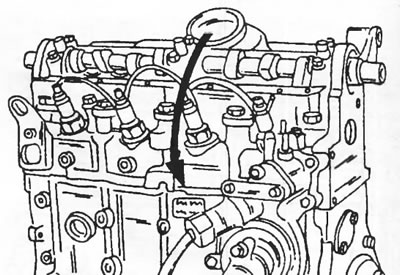
Figure 258. Installing the cylinder head. Tilt the cylinder head in the direction of the arrow…

Figure 258. Installing the cylinder head. Tilt the cylinder head in the direction of the arrow after inserting the centering sleeve from the other side.

  • Lubricate the bolt threads and washers with engine oil and insert the bolts. To tighten the bolts, use the socket from the Torx wrench set. Tighten the bolts in the sequence shown in Figure 259:
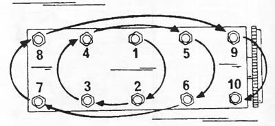
Figure 259. Cylinder head bolt tightening sequence.

Figure 259. Cylinder head bolt tightening sequence.


  • Tighten the bolts in the sequence shown to a tightening torque of 20 Nm.
  • Tighten the bolts in the sequence shown to a torque of 60 Nm.
  • After this, tighten the bolts in the specified sequence without a torque wrench to a certain angle. The rotation angle is 180°, or half a turn. This angle can easily be maintained when installing the socket handle extension.
  • Further tightening is not required after a certain engine mileage.
  • Install the camshaft timing pulley. While holding the pulley from turning, tighten the bolt to a torque of 45 Nm.
  • Adjust valve clearances (section 16.3.5).
  • Turn the camshaft timing pulley to position (4) figure 247, which allows an M8x40 mm bolt to be inserted. This positions the toothed pulley so that the timing belt can be installed correctly.
  • Tighten the timing belt tensioner bolt (2) to a torque of 20 Nm (Figure 260).

[Article based on material from the website: peugeotbook.ru]
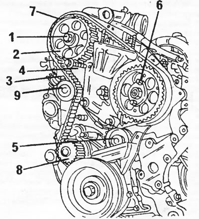
Figure 260. Installing the timing belt 1. Bolt, 45 Nm; 2. Timing pulley of the camshaft; 3. Bolt,…

Figure 260. Installing the timing belt 1. Bolt, 45 Nm; 2. Timing pulley of the camshaft; 3. Bolt, 20 nm; 4. Bolt, 20 nm; 5. Guide roller; 6. Toothed pulley of the high-pressure fuel pump; 7. Toothed belt; 8. Water pump pulley; 9. Belt tension roller


  • Connect the muffler pipe to the exhaust manifold.
  • Connect all pipes and hoses of the cooling and writing systems, as well as electrical wires to the cylinder head. Connect the cable to the idle speed increase device on the high pressure fuel pump.
  • Check that all parts in contact with the timing belt are free of oil and grease.
  • Check that the timing belt tension roller is fully pressed outward, i.e. secured in this position. Both timing belt rollers must rotate freely and not jam.
  • Lock the toothed pulley of the high-pressure fuel pump by installing two M8x40 mm bolts (7) and (9) on figure 247. In this case, the fuel pump is in the position of the injection moment of the first cylinder.
  • Lock the crankshaft at top dead center by inserting the locking rod from the rear into the flywheel as shown figure 246.
  • Apply the timing belt. First place the belt on the crankshaft toothed pulley, then on the rigidly fixed guide roller (5) in Figure 260, on the high-pressure fuel pump toothed pulley (6) and on the camshaft toothed pulley (2). Then, having tensioned the belt, place it on the other side on the water pump pulley (8) and finally on the tension roller (9).
  • Check the engagement of the timing belt teeth with all toothed pulleys.
  • Screw the bolt with the washer into the end of the crankshaft and temporarily tighten the bolt.
  • To release the tension roller, loosen the bolt (1) and nut (2).
  • Remove all locking bolts.
  • To align the position of the timing belt, turn the crankshaft in the working direction of rotation for at least two revolutions without interruption or changing the direction of rotation.
  • Loosen the bolt and nut again in Figure 261. This will set the tension roller to the belt tensioning position. In this position, tighten the bolt (1) and nut (2) to a torque of 18 Nm.
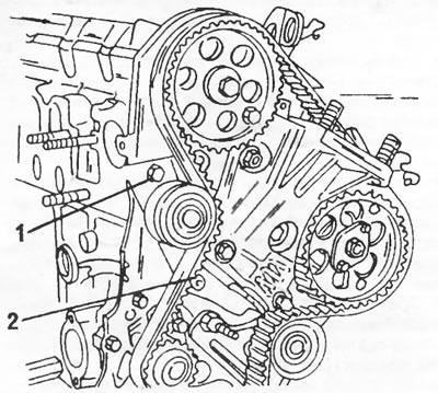
Figure 261. Loosen and retighten the bolt (1) and nut (2) as described in the text.

Figure 261. Loosen and retighten the bolt (1) and nut (2) as described in the text.


  • Turn the engine over a few revolutions and reinsert the timing drive lock bolts. If the bolts are difficult to insert, the valve timing is out of adjustment and must be adjusted again.
  • Remove the bolt and washer from the crankshaft.
  • Install both timing belt covers.
  • Place the crankshaft toothed pulley on and tighten the bolt with the washer. Coat the bolt threads with Loctite.
  • While holding the crankshaft from turning, tighten the timing pulley to a torque of 40 Nm. From this position, tighten the bolt an additional 60°.
  • All other work is carried out in reverse order.
This article is available at russian, bulgarian, belarusian, ukrainian, serbian, croatian, romanian, polish, slovak, hungarian
Article reviewed by editor: Bespalov Alexey
Share information:
Previous
Peugeot J5: Engine repair (DB9)
Next

Cylinder head assembly
Disassembling the cylinder head
Cylinder head
Engine assembly
D9B 1.9L Diesel Engine Disassembly
Adjusting valve clearances
Pistons and connecting rods
Disassembling pistons and connecting rods
Checking pistons and connecting rods
Assembly of pistons and connecting rods
See similar information for other Peugeot models

➨ Cylinder head cover — removal and refitting Peugeot 106 (1991-2003)
➨ Cylinder head (petrol engines 1.4 and 1.6 l, EPZ, TU5) Peugeot 207 (2006-2014)
➨ Installing the cylinder head Peugeot 306 (1993-2002)
➨ Installing the cylinder head Peugeot 405 (1987-1997)
➨ Cylinder head — removal Peugeot 605 (1989-2000)
Link to this article in different formats
Comments and feedback from visitors
No comments yet


Add two numbers 19 + 14


Partner I (1996-2008) 
  • General information
  • Introduction to the guide
  • Faults en route
  • Weekly checks
  • User manual
  • Maintenance (petrol)
  • Maintenance (diesel)
  • Power unit
  • Petrol engines
  • Diesel engines «XUD»
  • Diesel engines «DW»
  • Overhaul of petrol engines
  • Overhaul of diesel engines
  • Cooling and heating
  • Power and exhaust (petrol)
  • Power and exhaust (XUD diesels)
  • Power and exhaust (DW diesels)
  • Emission reduction
  • Starting and charging system
  • Transmission
  • Clutch
  • Mechanical gearbox
  • Drive shafts
  • Chassis, running gear
  • Brake system
  • Car suspension
  • Steering
  • Body and interior
  • Exterior (external elements)
  • Interior (internal elements)
  • Doors, locks and windows
  • Electrical equipment
  • Equipment and devices
  • Electrical circuits
Peugeot 807 (2002-2014) 
  • General information
  • Operating instructions
  • Maintenance
  • Troubleshooting
  • Power unit
  • Gasoline engines
  • Diesel engines
  • Cooling and heating
  • Fuel injection (petrol)
  • Fuel system (diesel)
  • Fuel system
  • Exhaust system
  • Ignition system
  • Transmission
  • Clutch
  • Manual gearbox
  • Automatic gearbox
  • Chassis, running gear
  • Brake system
  • Car suspension
  • Steering system
  • Body and interior
  • Exterior (external elements)
  • Interior (internal elements)
  • Electrical equipment
  • Power devices
  • Electrical circuits
Peugeot 806 (1994-2002) 
  • General information
  • User manual
  • Maintenance
  • Power unit
  • Petrol engines
  • Diesel engines
  • Lubrication system
  • Cooling system
  • Fuel injection (petrol)
  • Fuel system (diesel)
  • Ignition and exhaust systems
  • ECM Bosch Motronic MP 3.2
  • ECM Magneti-Marelli (MM)
  • Transmission
  • Clutch
  • Mechanical gearbox
  • Chassis, running gear
  • Brake system
  • Car suspension
  • Steering
  • Electrical equipment
  • Equipment and devices
  • Electrical circuits
Peugeot J5 (1981-1993) 
  • General information
  • Introduction to manual
  • Specifications
  • Gasoline engine
  • Engine repair
  • Lubrication system
  • Cooling system
  • Fuel system
  • Ignition system
  • Diesel engine
  • Engine repair (DB9)
  • Lubrication system (DB9)
  • Cooling system (DB9)
  • Fuel injection (DB9)
  • Engine repair (U25)
  • Lubrication system (U25)
  • Cooling system (U25)
  • Fuel injection (U25)
  • Transmission
  • Clutch
  • Gearbox
  • Drive shafts
  • Chassis, running gear
  • Steering system
  • Car suspension
  • Brake system
  • Electrical equipment
  • Power devices
  • Electrical circuits
PeugeotBook.ru © 2018–2026 | Mobile version | Sitemap: EN BG BY UA RS HR RO PL SK HU | Write message | Site search | Add to bookmarks | Peugeot owners
106 (1991-2003) | 206 (1998-2012) | 207 (2006-2014) | 305 (1977-1989) | 306 (1993-2002) | 307 (2001-2008) | 405 (1987-1997) | 406 (1995-2004) | 605 (1989-2000) | Partner-I (1996-2008) | Eurovans-807 (2002-2014) | Eurovans-806 (1994-2002) | J5 (1981-1993) |
Cookies are used to ensure the correct display of pages on the site.