



Table of contents: Diesel engine 🠇 Turbodiesel engine 🠇
Thoroughly clean the threaded holes under the cylinder head. The holes must be degreased. If necessary, you can go through the threads with an M12 x 150 tap. After this, clean the threaded holes.
- Press the centering sleeve into the cylinder block from the rear in the location indicated on the figure 355.
- Determine the thickness of the cylinder head gasket as described above.
- Measure the length of the cylinder head bolts. All bolts whose length from the thread runout to the underside of the bolt head exceeds 121.5 mm for a diesel engine and 146.8 mm for a turbodiesel engine must be replaced because they have been stretched too far.
- Place the cylinder head at an angle so that the bore in the cylinder head can be aligned with the centering sleeve in the cylinder block. After this, lower the cylinder head forward. The installation of the cylinder head is shown in Figure 375.
- Lubricate the bolt threads and washers with engine oil and insert the bolts. To tighten the bolts, you need a Torx key head of a certain size. Tightening of the bolts is carried out in the sequence shown in Figure 376, however, the differences between a diesel and turbodiesel engine should be taken into account:
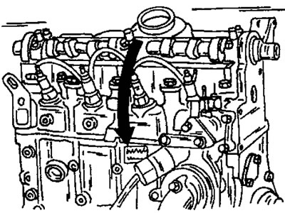
Figure 375. Installing the cylinder head. Lower the cylinder head in the direction of the arrow after the centering sleeve enters the hole from the other side.

Figure 376. Cylinder head bolt tightening sequence.
Diesel engine
- Tighten the bolts in the sequence shown in Fig. 376 to a tightening torque of 20 Nm.
- Tighten the bolts in the sequence shown in Fig. 376 to a tightening torque of 60 Nm.
- Then, in the sequence shown in Figure 376, tighten the cylinder head bolts by half a turn, or 180°, without a torque wrench. This is easily accomplished using a wrench extension.
- It is not necessary to tighten the bolts after the engine has warmed up.
Turbodiesel engine
- Tighten the bolts in the sequence shown in Fig. 375 to a tightening torque of 20 Nm.
- Tighten the bolts in the sequence shown in Fig. 376 to a tightening torque of 60 Nm.
- Then, in the sequence shown in Figure 34, tighten the cylinder head bolts to an angle of approximately 220°. Maintaining this angle without a protractor is more difficult on a turbodiesel engine than on a diesel engine. It should be assumed that 180° is half a turn, and 270° is three-quarters of a turn. From here an angle of 220° can be determined.
- No further tightening of the bolts is required.
- Install the camshaft timing gear. At the same time, hold the toothed pulley in an appropriate manner to prevent it from turning. Tighten the bolt to a tightening torque of 45 Nm.
- Adjust valve clearances (section 15.4.5).
- Turn the camshaft to a position where the M8x40 bolt can be inserted at location (4) in Figure 362. This sets the toothed pulley to the position required for applying the toothed belt.
- Tighten the timing belt tensioner bolt (2) to a torque of 20 Nm (Figure 377).
- Tighten the engine mount bracket bolt (2) to a torque of 20 Nm (Figure 377).
- Install the engine lifting eye.
- Connect the muffler pipe to the exhaust manifold.
- Connect all pipes and hoses of the cooling and fuel systems, as well as electrical wires, to the cylinder head. Connect the idle speed acceleration cable to the high pressure fuel pump.
- Check that there are no traces of oil or grease on all parts that come into contact with the timing belt.
- Check whether the timing belt tension roller is fully pressed outward, that is, that it is tightened in this position. Both timing belt tension rollers must rotate freely, i.e. not jam.
- Lock the high pressure fuel pump drive pulley by inserting two bolts (7) and (9) onto figure 362. In this case, the drive pulley is set to the fuel injection position of the first cylinder.
- Lock the crankshaft at top dead center by inserting the locking rod into the flywheel from the rear side as shown in Fig. 359.
- Apply the timing belt. First, place the belt on the crankshaft toothed pulley, then on the rigidly fixed guide roller (5) in Figure 377, the high-pressure fuel pump drive pulley (6) and the camshaft toothed pulley (2). Keeping the toothed belt tensioned, place it on the other side on the water pump pulley (8) and on the tension roller (9).
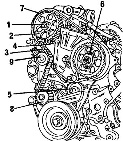
Figure 377. Installing the timing belt. 1. Bolt, 45 Nm; 2. Timing pulley of the camshaft; 3. Bolt, 20 nm; 4. Bolt, 20 nm; 5. Guide roller; 6. Toothed pulley of the high-pressure fuel pump; 7. Toothed belt; 8. Water pump pulley; 9. Belt tension roller
- Check the engagement of the belt with all toothed pulleys.
- Screw in and temporarily tighten the bolt with washer onto the end of the crankshaft.
- To release the tension roller, loosen the bolt (1) and nut (2).
- Remove all locking pins.
- To align the position of the timing belt, turn the crankshaft at least two revolutions - but in no case against the direction of engine rotation.
- Loosen the bolt and nut again in Figure 378. This will move the tensioner into the belt tension position. In this position, tighten the bolt (1) and nut (2) to a torque of 18 Nm.
- Turn the engine over several times and reinsert the timing locking rod. If the bolt is difficult to insert, then turn the engine again, since the position does not correspond to the specified one.
- Screw the bolt and washer back into the crankshaft. Pre-coat the bolt threads with Loctite paste.
- While supporting the crankshaft, tighten the belt pulley bolt to a torque of 40 Nm. From this position, tighten the bolt an additional 60°.

Figure 378. Loosen and retighten the bolt (1) and nut (2) as described in the text.

Figure 379. Installing the timing belt cover. 1. Upper protective cover; 2. Lower protective cover; 3. Hairpins; 4. Spacer sleeve
All other work is carried out in reverse order. Some tightening torques need to be specified:
- Engine mount - 45 Nm
- Intake manifold - 25 Nm
- Turbocharger - 55 Nm.