



Table of contents: Valves 🠇 Valve seats 🠇 Valve springs 🠇 Valve guide bushings 🠇 Cylinder head 🠇 Camshaft 🠇
It is assumed that the parts have already been removed from the cylinder head, that is, the cylinder head looks as shown in Figure 367.
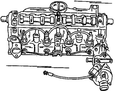
Figure 367. Cylinder head before disassembly.
- Remove all camshaft covers. Remove both oil seals from the front and rear. These seals must be replaced. Figure 338 shows the work steps at this stage of disassembly.
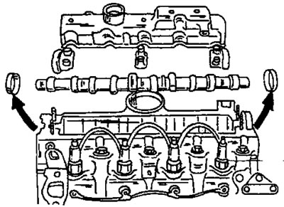
Figure 368. Disassembling the cylinder head.
To remove the valves from the cylinder head, a special valve puller is required. One such puller is shown in Figure 93, which, however, may not necessarily be of this type.
If you don't have a valve puller, you can also remove them as follows:
- Place a wooden block into the combustion chamber so that it rests against the valve being removed.
- Place a tube of the same diameter as the valve spring plate on the top side of the valve spring and hit the tube sharply with a hammer. At the same time, the valve spring is compressed and both valve crackers pop out.
- Remove the parts from the valve and pull the valve out from the other side of the cylinder head. Immediately mark the location of the valve installation and set the valve aside accordingly.
- Check the parts according to the following instructions to ensure they are reinstallable.
Valves
Minor damage to the valve surfaces can be repaired by lapping the valve in the seat following the instructions in subsection "Valve seats". Measure the valve to ensure it matches the dimensions and adjustments table and replace any valves that do not match the values specified in the table.
- If the ends of the valve stems are worn, they can be ground on a grinding machine, provided that the correction does not require removing more than 0.50 mm of material.
- Valve heads may be ground on a grinding machine provided that the head thickness specified on the figure 94 arrows, becomes no thinner than 0.5 mm. This also applies to the diesel engine.
- Check the valve stems and, in this connection, the internal diameter of the valve guides, for which a micrometer is required. To do this, measure the valve stems in several places, as shown in figure 95, and record the measurement results. After this, measure the inner diameter of the valve guide bushings as shown in figure 96. If there is wear, i.e. when the difference in measurement results is more than 0.10 mm, the valve guides should be replaced (see subsection "Valve guides").
View the original on the website (PeugeotBook.ru)
Valve seats
- Check all valve seats for signs of wear or scarring. Minor signs of wear can be eliminated with a 45° cutter. The inlet and outlet valves have the same valve. But if the seats already have significant wear, they should be re-milled or the valve seat rings need to be replaced. The latter work requires drilling the valve seat holes and should therefore be carried out at a Peugeot service station.
- When installing new valve guides, additional milling of the valve seats is required. This requires an angle cutter (Figure 97), which should be suitable for both intake and exhaust valves:
- Mill the valve seat corner, then lightly mill the top side of the seat with a trimming cutter to reduce the valve seat width to 1/45 mm for intake valves and 18 mm for exhaust valves. Once this width is reached, the milling work is completed.
- Lapping the machined valve seats. To do this, rub in a little grinding paste and insert the valve into the corresponding seat. Place a suction cup on the valve and move the valve in both directions as shown figure 98.
- After lapping, carefully remove any remaining dirt and paste from the parts and check the valve seat on the valve head and in the seat ring. Both pieces should show a continuous matte ring that defines the width of the saddle.
- Apply a few strokes on the valve head ring with a pencil. Apply strokes around the circumference at intervals of approximately 1 mm. Then, carefully lower the valve into the seat and rotate the valve 90°, applying slight pressure.
- Remove the valve and check if the pencil marks have been removed from the valve seat. If the valve seat width is within the specified limits, the head can be installed on the vehicle. Otherwise, the valve seats will need to be treated or, in the worst case, the cylinder head will need to be replaced. In this case, it is necessary to remove all parts from the old cylinder head and transfer them to the new head.
On a diesel engine, the following should also be taken into account:
To avoid collision with the pistons, the valve heads must be located at a certain depth below the cylinder head surface. In Figure 369 this size is indicated by arrows. For intake valves, this size is 0.50–1.05 mm, for exhaust valves 0.90–1.45 mm. If milling is required to clean the valve seats, the seat is seated too deep in the cylinder head. The way out of this situation is to press in a new valve seat ring or install a new cylinder head. To control the installation depth of the valve heads, the following work is performed:
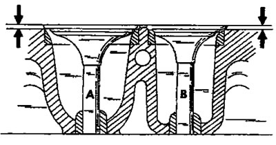
Figure 369. The valve head should be positioned below the cylinder head surface by the dimension indicated by the arrows. The dimensions for the intake valves "A" and the exhaust valves "B" are not the same.
- Mill the valve seats in small portions, remove the metal shavings and insert the valve into the hole.
- Place it on the cylinder head surface on the appropriate stand, as shown in Figure 370, and rest the indicator feeler gauge against the cleaned surface of the cylinder head. The figure shows the dial gauge used at Peugeot service stations, but any dial gauge with a suitable stand will do. Reset the indicator scale to zero.
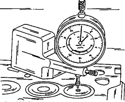
Figure 370. Location of the dial indicator for measuring the valve installation height.
- Without changing the installation position of the dial indicator, move the dial indicator probe to the upper side of the valve head. The scale indicates how far the valve is below the surface of the cylinder head. The figure shows the measurement on the exhaust valve, which is the smaller of the two valve types.
- Repeat the same check for the intake valves.
- Evaluate the measurement results and, if necessary, continue milling or install new valve seat rings. However, before making a decision, you should check for cylinder head distortion.
- To replace valve seats, you need to drill out the old seat rings. Since this is a responsible job, it should be entrusted to a service station.
- The same measurements should be made with the prechamber inserts. To do this, place the indicator's measuring probe on the edge of the pre-chamber. The prechamber insert should protrude by 0 to 0.3 mm (Figure 371). If this is not the case, the prechambers need to be replaced.
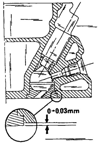
Figure 371. The pre-chambers must protrude above the cylinder head surface by the specified size.
Valve springs
Everything stated about valve springs for gasoline engines also applies to diesel engines. Valve springs are color-coded and when replacing, only springs of the same color code should be installed.
Valve guide bushings
To accurately measure valve guides and valve stems, a micrometer is required, the use of which was described in the gasoline engine section. If the difference between the two measurements exceeds 0.10 mm, the corresponding valve guide bushing must be replaced (or all guides). If a micrometer is not available, the valve stem clearance in the guide bushings can also be determined as described for gasoline engines (see also figures 95 and 96).
- Before replacing the valve guide, check the general condition of the cylinder head. Cylinder heads with small cracks between the valve seats can be ground, provided that the cracks are really small.
- To replace the valve guide, press out the old guide using a suitable punch. To press out the guide bushings, it is necessary to heat the cylinder head in hot water. Before pressing out, measure the height of the guide sleeve protrusion above the cylinder head surface. The neck at the end of the drift should be machined so that it fits into the guide bushing.
- When replacing the guide bushings, the valves are also replaced at the same time. After this, it is necessary to grind the valve seats. There are guide bushings with increased diameters, accordingly, it is necessary to drill the receiving holes for the guides in the cylinder head.
- Generously lubricate the guide bushings with engine oil and press them into the cylinder head to the protrusion value measured before removing the old guide bushing.
- After pressing in, ream the valve guide bushings to a diameter of 8.00 mm + 0.022 mm. Use an adjustable reamer for this. This automatically creates the required clearance of the valve stems in the guide bushings.
When replacing the valve guide, milling of the valve seats is required.
Cylinder head
Thoroughly clean the cylinder head and cylinder block surfaces and check for distortion of the cylinder head surface. To do this, place a measuring ruler along, across and diagonally on the surface of the cylinder head and use a feeler gauge to measure the clearance between the ruler and the cylinder head. If the feeler gauge passes through a thickness of more than 0.03 mm, as shown in Figure 372, the cylinder head should be given for flat milling. If the clearance is greater in any place, the cylinder head must be replaced, as it can no longer be milled.
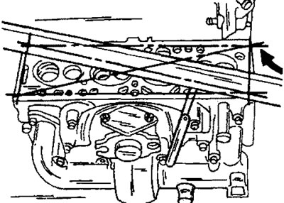
Figure 372. Checking cylinder head tilt.
The cylinder head can be milled if it is necessary to remove metal no more than 0.02 mm, however, the following features should be taken into account.
Some cylinder blocks are marked with the letter "R" in the location shown in Figure 373. This indicates that the cylinder block has already been milled to an oversize size. With this type of cylinder block, when installing the cylinder head, a thicker cylinder head gasket must be installed, which also has an "R" marking in the specified location. If it turns out that milling of such a cylinder head is required, you should contact a Peugeot service station.
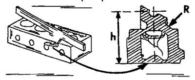
Figure 373. Location of the "R" marking on the cylinder block and on the cylinder head gasket. The height of the head "h" is measured between the arrows.
Before deciding to reinstall the cylinder head, measure its height between the contact surfaces ("h", Figure 373). It should be 140 mm with a small tolerance. The head marked "R" must have a height of 140.75 mm.
Camshaft
Camshafts are not the same on all engines and, in order not to disrupt the operation of the valve timing mechanism, the correct camshaft must be installed when replacing.
Place the camshaft end journals into the prisms as shown in figure 102 for a gasoline engine camshaft, or clamp it in the centers of a lathe and place the measuring probe of the dial indicator against the middle journal of the bearing. Slowly turn the camshaft and read the dial indicator scale. If the reading exceeds 0.01 mm, the shaft is bent and must be replaced.
Check the bearing journals for visible damage. If damage is detected, further work may not be carried out. All bearing journals have different diameters.