



- Raise the front of the vehicle and remove the right front wheel.
- Disconnect the wires from the battery and remove the battery.
- Drain the coolant from the cooling system. To do this, unscrew the plugs on the cylinder block and on the radiator. If the coolant is not yet old, drain it into a clean container. The coolant contains antifreeze and can be reused if it has not been in the cooling system for a long time. Otherwise, the disposal of the coolant is carried out in compliance with environmental protection regulations.
- Remove the large air distribution box in the middle of the engine compartment. On a turbodiesel engine, the charge air cooler is located in this location and must be removed in this case. Figure 360 shows the location of the air distribution box. Position (2) in the figure is the so-called vibroinertial mass. It should also be removed.
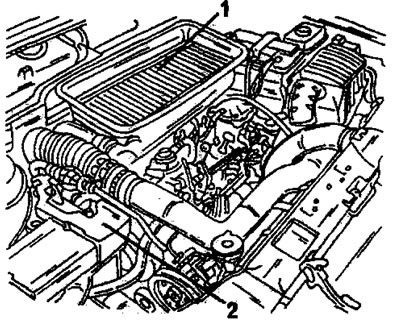
Figure 360. Engine compartment. Parts (1) and (2) must be removed.
- There is a relay box next to the battery. Disconnect all connected electrical wires and move them to the side.
- The following work is performed using Figure 361. Unscrew the lever bracket (1) and remove the fuel filter (2). Unscrew the bolt (3) in the middle of the filter housing.
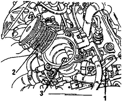
Figure 361. Remove the engine lifting bracket (1), fuel filter (2) and unscrew the bolt (3).
- Unscrew the battery tray.
- Loosen the cooling system fitting bolts and remove the fitting.
- Release the hose connection locks in accordance with the data in the section "Heater" or section 15.1 and remove all hoses between the engine and the body.
- Disconnect all electrical wires between the engine or cylinder head and the body. This includes glow plug wires, fuel shut-off devices, temperature sensor wire for display on the instrument panel, temperature switch wires, etc.
- Place a jack under the engine and lift it up so that it is under slight tension.
- Remove the engine mount (Figure 331) from the timing drive side. On a turbodiesel engine, first remove the stop from the support bracket.
- Disconnect the throttle cable. For more details on this, see:. chapter "Diesel engine fuel injection device".
- Disconnect the fuel supply and drain hoses. One of the hoses is shown at position 51 in Figure 324, the second hose (2), which is connected to the hand pump, is disconnected from the pump.
- Unscrew the muffler pipe from the exhaust manifold. To do this, unscrew the two nuts with cups from the bottom side and pull out the springs. Disconnect the connection. To ensure a tight connection, when the nuts are tightened to the required tightening torque, the springs are compressed. There are three gear shift rods located near the muffler (Figure 327). They should be pressed away from the levers by inserting a screwdriver behind the ball joints.
- Remove the shield from the wheel arch.
- Unscrew and remove both timing belt covers from the front of the engine. Also remove the casing from the bottom side.
- Insert the locking rod into the engine crankcase at the location shown in Figure 359. Pre-turn the crankshaft to the top dead center position.
- Remove the expansion tank of the cooling system.
- Prepare three M8 x 40 bolts. Insert one of the bolts into the camshaft pulley at location (4) in Figure 362, and insert the other two bolts into the high-pressure fuel pump drive pulley at locations (6) and (7). With the crankshaft correctly positioned, the bolts can be inserted without difficulty. In this case, the gas distribution mechanism is blocked.
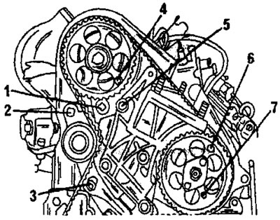
Figure 362. Front side of the engine with details for removing the timing belt. 1. Square hole; 2. Belt tensioner bolt; 3. Belt tensioner bolt; 4. Inserted locking rod; 5. Engine mount bolt; 6. Inserted locking rod; 7'. Inserted locking rod
- Loosen the bolts (2) and (3) of the belt tensioner. Insert an extension with a square of the appropriate size into the square hole (1) and move the tension roller outward to compress the springs of the automatic belt tensioner. This is a four-sided adapter from a set of key heads with a 3/8-inch drive. Re-tighten the bolt (2) in Figure 362 to hold the tensioner in the new position.
- Carefully remove the timing belt forward from the timing pulleys.
- For a turbodiesel engine, tilt the engine forward and place a wooden spacer between the engine and the body in the place shown in Figure 363. Also, for this engine, loosen the bolt (1) in Figure 364 without unscrewing it and remove the intake manifold. Loosen the three turbocharger mounting bolts and remove the turbocharger.
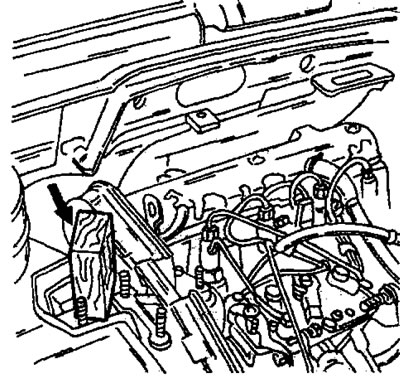
Figure 363. For a turbodiesel engine, place a wooden spacer in the indicated location to avoid damage to the engine.
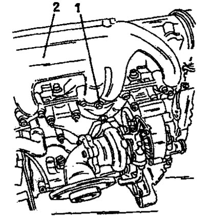
Figure 364. Loosen the bolt (1) and remove the intake manifold 92) of the turbodiesel engine. Remove the turbocharger as well.
- Loosen the camshaft toothed pulley mounting bolt and remove the toothed pulley together with the inserted bolt from the shaft. When unscrewing the bolt, hold the toothed pulley.
- Unscrew the cylinder head cover.
- Disconnect the fuel injection pipes.
- In several passes, in the reverse order to that shown in Figure 365, unscrew and remove the cylinder head bolts. Before reinstallation, measure the length of the bolts, i.e. do not install bolts with an unacceptable length.
[Original published on the portal: peugeotbook.ru]
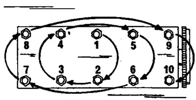
Figure 365. Cylinder head bolt tightening sequence. Loosen the bolts in reverse order.
- Because the cylinder head sits on a centering sleeve, it can be difficult to remove. At Peugeot service stations, two bent levers are used for this purpose, inserted into two holes for the cylinder head bolts. You can make such levers yourself and use them to remove the cylinder head from the cylinder block, as shown in Figure 366. To release the head, lift the head with both levers. After this, move the head to the side to pass the camshaft through the rear plate of the toothed pulley. Immediately check where the centering sleeve is located. If it remains in the cylinder head, it must be pulled out and hammered into the cylinder block before installation.
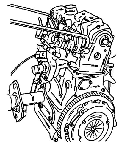
Figure 366. Using the levers specified in the text to lift the cylinder head. Dismantling is shown on a removed engine.
- Clean the contact surfaces of the cylinder head and cylinder block with a suitable cleaning fluid. Never clean surfaces with a scraper or sandpaper. Additional grinding of the cylinder head surface is not permitted. If the camshaft rotates freely, no further work is required.
- After removing the cylinder head, remove all parts from it and remove the valves in the usual manner, as described in the relevant section.