



- Before assembly, check that the parts are clean and free of foreign inclusions.
- Apply a layer of grease to all rotating and moving parts. This should be done before assembly, not after, as this will prevent the lubricant from reaching the areas where the parts come into direct contact. It is especially important to generously lubricate the pistons, piston rings, and cylinder walls with engine oil.
- Thoroughly clean all cylinder block parts if the engine has been completely disassembled. When partially disassembling, do not allow foreign objects to enter the disassembled engine parts or cavities. To avoid this, all holes should be either sealed or covered with rags.
- It is best to blow out lubrication channels and lubrication holes with compressed air. If there is no compressed air line, clean the lubrication channels and lubrication holes with a wooden stick, under no circumstances using metal objects. Under no circumstances should you skimp on parts or reinstall parts that were initially damaged.
- The size and adjustment tables provide wear limits for most moving parts. If in doubt or when approaching the wear limit, it is recommended to replace the part, saving on another engine disassembly in the near future.
- All spare parts should be purchased only from Peugeot dealerships, indicating the engine number. Since modernisation and consequent modification of individual parts are constantly taking place, only the Peugeot supplier is able to select the required spare part.
- Assemble the pistons and connecting rods according to the instructions in section 15.5.3.
- Insert the connecting rod bearing shells into the connecting rods in accordance with the markings in Figure 346 (when installing the previous parts). The guide tabs of the bearing shells must fit into the cutouts in the connecting rod holes.
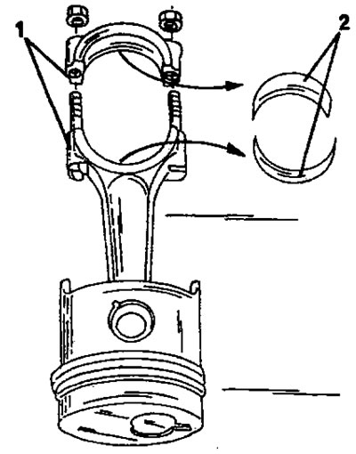
Figure 346. Piston.
The connecting rod and bearing cover are marked on opposite sides (1).In accordance with this, insert the bearing inserts 92).
- Apply both crankshaft end play adjusting half washers to each side of the second crankshaft main bearing (the first bearing is located next to the clutch). The lubrication holes of both halves of the washers must face outward on each side, that is, towards the crankshaft cheeks. Lubricate the washers well with engine oil. Figure 347 shows the arrangement of the parts.
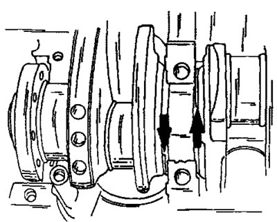
Figure 347. Here, spacer washers are inserted to adjust the axial play of the crankshaft.
- Carefully insert the crankshaft into the bearing shells. The working surfaces must be well lubricated with engine oil. To do this, use an oiler and rub the oil in with your finger; do not use a brush to apply the oil.
- Install the bearing caps in the same order with the bearing shells inserted (bearing cap #2 has spacer washers). The bearing caps are numbered, and the numbers on the caps should face the oil filter. Do not install the bearing cover on the flywheel side yet.
After this, check the axial play of the crankshaft:
- Install a dial indicator on the appropriate stand at the front of the engine and attach the feeler gauge to the crankshaft boss, as shown in Figure 348. If the dial indicator has a stand with a magnet, the stand can be installed on the shaft and the feeler gauge can be attached to the ground surface of the block.
(Original published on the portal: Peugeotbook.ru)
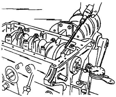
Figure 348. Measuring the axial play of the crankshaft.
- Press the crankshaft with a screwdriver in one direction and reset the dial indicator scale to zero.
- Press the crankshaft in the other direction and read the reading from the dial indicator scale. The value should be within the range of 0.07 - 0.32 mm.
- If the axial play exceeds the specified tolerance, two oversized half washers must be installed. Both washers must be the same thickness. In addition to the nominal size of 2.30 mm, larger washers are available in sizes 2.35, 2.40, 2.45 and 2.50 mm. it is important that both washers of the same thickness are installed in the same direction to avoid pressing the crankshaft to the same side.
- Now, to install the rear bearing cover, a special tool is required to install the side seals of the cover. First, cover the surfaces of the engine crankcase under the cover with sealing compound.
- Screw two guide plates onto the tool as shown in Figure 349. Tighten the bolts by hand only.
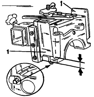
Figure 349. Tool for installing the rear crankshaft bearing cover. Two guide plates (1) press the side seals into the grooves. The seals must have the specified protrusions.
- Hold two new rubber seals with a holder. Secure the holder with one bolt to the bearing cap and lubricate the guide plates with engine oil.
- Press both guide plates together with your hands and insert them all at a slight angle into the cylinder block until the cover is seated. To do this, press the tool down.
- Insert both cover bolts and tighten them by hand.
- Unscrew the tool from the cover and pull it out together with the guide plates from the cylinder block.
- Tighten the bearing cap bolts evenly from the inside out to a tightening torque of 70 Nm.
- Screw two bolts into the crankshaft flange (flywheel mounting bolts) and insert a screwdriver between the bolts. Turn the crankshaft with a screwdriver to check that the shaft is not jammed. Check the jammed shaft immediately before continuing to assemble the engine.
- Lubricate the new oil seal on the outside with engine oil and press the oil seal into the rear of the cylinder block. Be careful not to damage the seal.
- Sort the assembled pistons and connecting rods by numbers. Place a tension band on the first piston and insert the pistons into the cylinder bores, which are well lubricated with engine oil, according to the markings (Figure 350). At the same time, move the connecting rod so that it fits onto the crank pin. If bearing shells are reinstalled, do not mix them up. After installation, check whether the recess is in the specified position. Install the piston of the fourth cylinder in the same way.
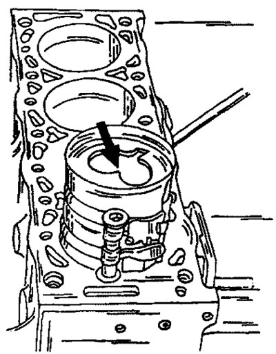
Figure 350. Installing pistons. Apply the clamping band in the manner shown and push the piston down in the direction shown until the clamping band can be removed.
- Insert the bearing shells into the bearing caps of both installed connecting rods in accordance with the markings. Lubricate the bearing surfaces thoroughly with motor oil. Re-install the bearing shells into the corresponding connecting rod bearings. Tighten the caps to a torque of 50 Nm.
- Turn the crankshaft until the other connecting rod journals reach the lower position and install the other two pistons with connecting rods in the described manner. After installation, check again that the crankshaft is not jammed.
- Install the bearing shield with a new gasket from the front side. Tighten the bolts to a torque of 10 Nm.
- When installing the oil pump, place the drive chain on the oil pump sprocket, install the oil pump and insert the spacer plate between the pump and the cylinder block, that is, in the reverse order of removal in Figure 342.
- Tighten bolts (1), (2) and (3) in Figure 351 to a tightening torque of 13 Nm. The bolts are of different lengths. Bolt (1) is the shortest, bolt (2) is the longest, and bolt (3) is the average length.
- Carefully press the seal flush into the bearing shield using a suitable rod. Select a suitable rod that fits flush with the seal along the entire outer surface, as shown in Figure 352.
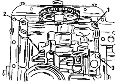
Figure 351. Location of oil pump mounting bolts. The bolts have different lengths.
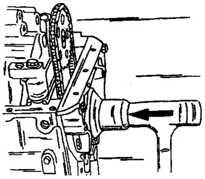
Figure 352. Pressing in the crankshaft oil seal from the timing drive side.
- Cover the contact surfaces under the oil pan with sealing compound and install the oil pan with a new gasket. Install 23 bolts and tighten evenly in a circle to a torque of 13 Nm.
- Install the flywheel onto the crankshaft. At the same time, turn the flywheel on the crankshaft flange until all holes align. Bolts must be replaced. Coat the bolt threads with locking paste. When tightening the bolts, hold the flywheel from turning in the manner shown in Figure 335. Tighten the bolts evenly to a torque of 50 Nm.
- Place the driven clutch disc into the flywheel and install the clutch basket. The long side of the driven disc hub must face outward. Turn the drive disk until both markings align (when reinstalling the old parts) and screw in the bolts. A centering shaft is required to install the clutch. This work operation is described in detail in the "Clutch" section. Hold the flywheel in place as described above and tighten the bolts crosswise to 22 Nm. Check the free axial movement of the centering shaft.
- Cylinder head gaskets come in different thicknesses, and the thickness of the head gasket you install depends on how much the pistons protrude from the cylinder head. To determine the thickness of the cylinder head gasket, it is necessary to sequentially set all pistons to the top dead center position.
- It should be taken into account that the thickness of the cylinder head gasket varies on diesel and turbodiesel engines:
- Place a magnetic-based dial indicator on the cleaned surface of the cylinder block, and place the feeler gauge on the surface at the edge of the piston. In this position, reset the dial gauge scale to zero. This measurement process is shown in Figure 353.
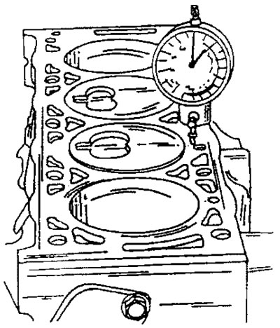
Figure 353. The first stage of measuring the piston protrusion above the cylinder block surface.
- Leaving the magnetic base of the indicator in the same place on the surface of the cylinder block, move the measuring pin as close as possible to the center of the piston bottom. This measurement process is shown in Figure 354.
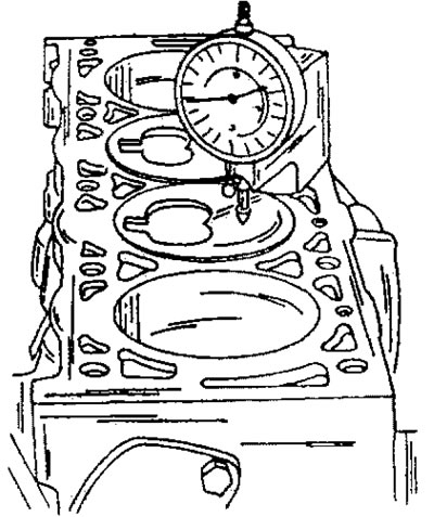
Figure 354. Move the measuring pin as close to the center of the piston bottom as possible. The displayed value is the piston protrusion above the cylinder block surface.
- In the same way, take measurements on the remaining pistons and record the measurement results.
- The thickness of the gasket is determined by the maximum measurement result, however, the difference in measurements of individual pistons should not exceed 0.12 mm.
- The size of the protrusion is now determined as follows:
- If the measurement result is between 0.54 and 0.65, a cylinder head gasket with a thickness of 1.49 mm on diesel engines or 1.50 mm on turbodiesel engines should be installed. The diesel engine gasket has a notch as shown in Figure 355. The turbodiesel engine gasket is marked as shown in Figure 356. The nominal thickness gasket has one notch on the edge.
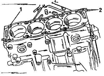
Figure 355. Cylinder head gasket applied. Install the centering pin (1) in the specified location. The cylinder head gasket notches are located at (2).
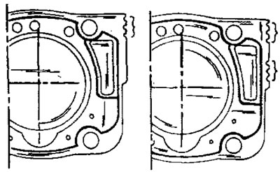
Figure 356. Cylinder head gasket. On the left is a diesel engine gasket, on the right is a turbodiesel engine gasket. The last gasket has two notches.
If the measurement result is between 0.65 and 0.77, a cylinder head gasket with a thickness of 1.61 mm on diesel engines or 1.60 mm on turbodiesel engines should be installed. This gasket has two notches on the edge.
- If the measurement result is between 0.77 and 0.32, a cylinder head gasket with a thickness of 1.73 mm on diesel engines or 1.70 mm on turbodiesel engines should be installed. This gasket has three notches on the edge. It should be noted that the gaskets of turbodiesel engines have two sets of notches in the place shown in Figure 356.
- After measuring the piston protrusions, before proceeding with further assembly, rotate the crankshaft to a position where all pistons are installed in the middle position in the cylinders.
- Check that the centering pin (1) in Fig. 356 is in the cylinder block and install the cylinder head as described in the relevant section. Adjust valve clearances immediately (see the relevant section).
- Install the water pump with a new gasket and tighten the bolts to a torque of 15 Nm.
- Screw both temperature switches into the thermostat housing. Their location is shown in Figure 357.
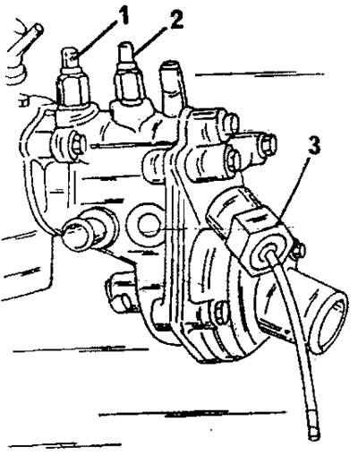
Figure 357. Location of temperature switches in the thermostat housing. The switch (1) is not always installed.
- Lubricate the threaded part of the automatic fast idle speed regulator capsule (3) in Figure 357 with sealing compound and screw it into the cooling system fitting (30 Nm).
- Install the thermostat with two new gaskets into the housing. After this, secure the assembled thermostat housing to the cylinder head.
- Remove the camshaft timing pulley (it should still be on the shaft, since the valve clearances were set) and press in the camshaft seals without damaging the seals. Lightly lubricate the sealing lips of the oil seals.
- Install the camshaft timing pulley. Tighten the central bolt to a torque of 35 Nm. While doing this, hold the toothed pulley in a certain position to prevent it from turning. For example, you can insert a rod into the hole of the toothed pulley and rest it against the cylinder head.
- Install the high pressure fuel pump (see the relevant section).
- Turn the crankshaft, camshaft and high-pressure fuel pump drive pulley until the keys occupy the positions shown in Figure 358.
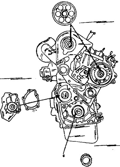
Figure 358. The arrows indicate the positions of the keys on the various shafts before applying the toothed belt.
- Install the high pressure fuel pump sprocket and tighten the central bolt. At the same time, hold the pulley from turning (insert the rod). Tighten the bolt to a torque of 50 Nm. Install the high-pressure fuel pump drive pulley retaining plate and tighten the two bolts to a torque of 12 Nm.
- Place the toothed pulley on the end of the crankshaft (do not displace the key) and drive it completely onto the shaft using a piece of pipe.
- Insert one of the M8 x 40 bolts used during disassembly into the camshaft toothed pulley at location (1) in Figure 338. The bolt enters the hole from the rear and locks the camshaft timing pulley when the timing belt is applied.
- Lock the high pressure fuel pump drive pulley in the same manner. This time, bolts (2) and (3) are inserted into the holes. Check that the pulley is locked.
- After this, the crankshaft should be adjusted. For this purpose, a metal rod with a diameter of 8 mm is used, which is inserted from the rear side of the cylinder block, as can be seen in Figure 359. In this case, the rod enters the hole in the flywheel and locks it in the desired position. The picture shows a special tool from Peugeot.
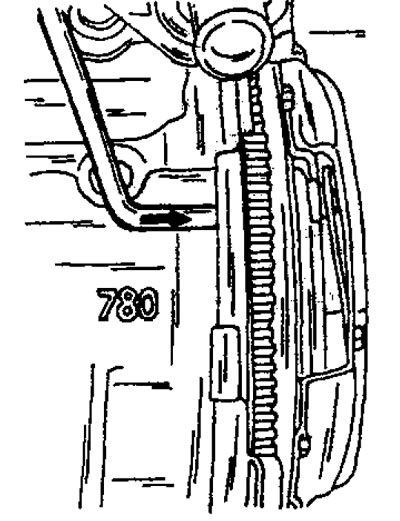
Figure 359. The crankshaft locking rod is inserted from the rear side of the engine crankcase in the indicated position.
- Apply the timing belt. First, the belt is placed on the crankshaft toothed pulley, then on the rigidly fixed idler pulley in the middle, the high-pressure fuel pump drive pulley, the camshaft toothed pulley, the tensioner pulley and finally on the water pump pulley. Check the engagement of the belt with all toothed pulleys. Tension the timing belt following the instructions in section 15.8.
- Adjust the injection position of the high pressure fuel pump in accordance with the instructions in the relevant section.
- Install the crankshaft belt pulley. Coat the bolt threads with Loctite. Tighten the bolt to a torque of 40 Nm and then tighten it another 60° from this position. The crankshaft must be locked.
- Screw in the glow plugs and tighten to a torque of 22 Nm. Place the distribution busbar onto the glow plug contact pins and tighten the nuts to a torque of 4 Nm.
- Screw in the injectors (90 Nm) and tighten the union nuts of the fuel injection pipes (20 Nm).
- Install timing belt guards. Using a powerful screwdriver, insert the spring bar in the middle.
- Install the oil filter and tighten it to a torque of 14 Nm. Before installing, generously lubricate the filter's rubber ring with engine oil.
- All other work is carried out in the reverse order: the tightening torque of the exhaust manifold fastening is 20 Nm, the tightening torque of the intake manifold fastening is 23 Nm.